Beam-column joint of a layered fabricated steel structure

A technology of beam-column joints and steel structures, which is applied in the direction of building construction and construction, can solve the problems of affecting construction speed and quality, affecting the mechanical performance of joints, and poor ductility of joints, so as to improve the efficiency of on-site assembly and facilitate on-site assembly , the effect of reducing workload

Inactive Publication Date: 2017-03-29
XI'AN UNIVERSITY OF ARCHITECTURE AND TECHNOLOGY
View PDF4 Cites 0 Cited by
  • Summary
  • Abstract
  • Description
  • Claims
  • Application Information

AI Technical Summary

Problems solved by technology

[0002] In the traditional fully welded beam-column joint, the upper and lower flanges of the beam and the web are welded to the column on site. Although this connection is a rigid connection, the ductility of the joint is poor, and brittle failure is prone to occur in earthquakes, and on-site welding is required, which greatly affects the construction. Speed ​​and quality are not suitable for fabricated steel structures. At the same time, due to the large welding area, it is easy to generate large residual stress, which affects the mechanical performance of nodes.
[0003] In traditional beam-column joints connected by high-strength bolts, the beam end seal plate and box-shaped columns are fastened and connected by high-strength bolts. When fastening, workers need to reach into the box-shaped columns. It is inconvenient, and the bolt holes will weaken the short column of the node, affecting its mechanical performance
[0004] In the traditional bolted and welded joint connection, the upper and lower flanges of the beam and column are welded to the column on site, and the web at the beam end is bolted to the column through a shear plate. This connection method requires on-site welding, which greatly affects the construction speed and quality. The program is complex and it is not easy to achieve rigid connection

Method used


Image

  • Beam-column joint of a layered fabricated steel structure
  • Beam-column joint of a layered fabricated steel structure
  • Beam-column joint of a layered fabricated steel structure

Examples


Embodiment 1

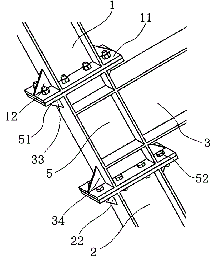
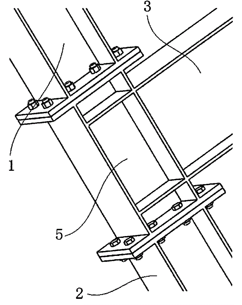
[0021] see Figure 1-3 , when the main beam 3, the upper column 1 and the lower column 2 are preferably I-shaped steel, one end of the main beam 3 is welded with a central column 5, and the central column 5 is also an I-shaped steel, and its upper and lower ends are respectively welded with a central column 5. The upper flange 51 of the column and the lower flange 52 of the middle column, the bottom of the upper column 1 is welded with the upper column flange 11 which is in contact with the upper flange 51 of the middle column, and the top of the lower column 2 is welded with a The lower flange 52 is connected to the lower column flange 21 .

[0022] An upper column stiffener 12 is welded between the upper column flange 11 and the upper column 1 .

[0023] A lower column stiffener 22 is welded between the lower column flange 21 and the lower column 2 .

[0024] The center column upper stiffener 33 is welded between the center column upper flange 51 and the center column 5 . ...

Embodiment 2

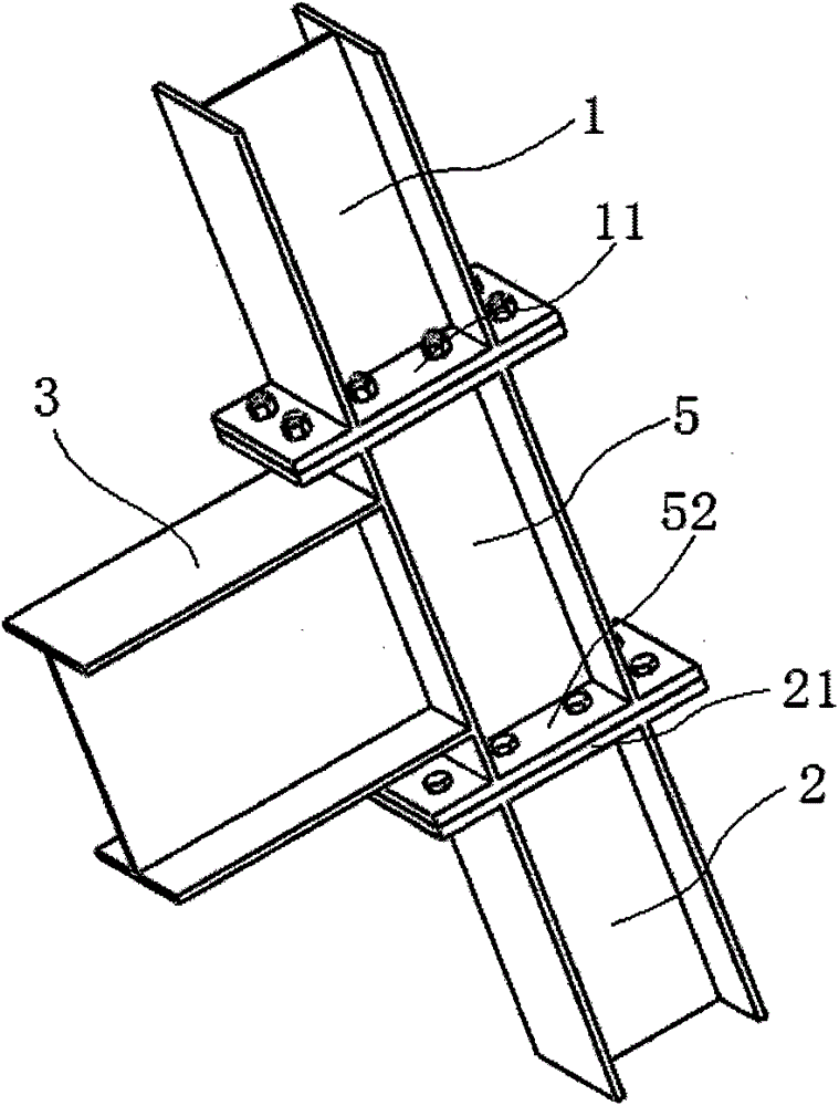
[0027] see Figure 4-5 When the main beam 3, the upper column 1 and the lower column 2 are preferably rectangular pipes, the central column 5 is a hollow rectangular tubular structure, and an upper end of the lower column 2 extends upwards to be plugged with the central column 5. Connecting the post 4, the connecting post 4 extends through the center column 5 to the upper column 1 through the gap, and the edges of the upper and lower ends of the center column 5 extend vertically outward respectively to the upper flange 51 of the center column and the lower method of the center column Flange 52, the bottom of the upper column 1 is welded with the upper column flange 11 docking with the upper flange 51 of the middle column, and the top of the lower column 2 is welded with the lower column flange 11 docked with the lower flange 52 of the middle column Lan 21.

[0028] An upper column stiffener 12 is welded between the upper column flange 11 and the upper column 1 .

[0029] A l...


PUM


Abstract

The invention discloses a beam-column joint of a layered assembled steel structure, which comprises an upper-layer column (1), a lower-layer column (2), and a main beam (1) installed between the upper-layer column (1) and the lower-layer column (2). 3); a middle column (5) is welded at the junction of the main beam (3) with the upper column (1) and the lower column (2), and a main beam (3) is welded on one side of the middle column (5), Its upper and lower ends are respectively welded with an upper flange (51) of a central column and a lower flange (52) of the central column, and the bottom of the upper column (1) is welded with an upper column that is opposite to the upper flange (51) of the central column. A flange (11), the top of the lower column (2) is welded with a lower column flange (21) which is connected with the lower flange (52) of the central column. The invention has simple structure, direct force transmission, clear force of each part, convenient industrialized manufacturing and on-site assembly, greatly reduced on-site assembly workload, improved on-site assembly efficiency, and low comprehensive cost.

Description

technical field [0001] The invention relates to the field of prefabricated building processing and manufacturing, in particular to a beam-column node of a layered prefabricated steel structure. Background technique [0002] In the traditional fully welded beam-column joint, the upper and lower flanges of the beam and the web are welded to the column on site. Although this connection is a rigid connection, the ductility of the joint is poor, and brittle failure is prone to occur in earthquakes, and on-site welding is required, which greatly affects the construction. The speed and quality are not suitable for fabricated steel structures. At the same time, due to the large welding area, it is easy to generate large residual stress, which affects the mechanical performance of the joints. [0003] In traditional beam-column joints connected by high-strength bolts, the beam end seal plate and box-shaped columns are fastened and connected by high-strength bolts. When fastening, wor...

Claims


Application Information

Patent Timeline
Patent Type & Authority Patents(China)
IPC IPC(8): E04B1/58
Inventor 郝际平刘宗全薛强朱钰锋卢俊凡孙晓岭
Owner XI'AN UNIVERSITY OF ARCHITECTURE AND TECHNOLOGY
Why Eureka
Try Eureka