
Diesel engine speed control device

A speed control device, diesel engine technology, applied in mechanical equipment, engine control, machine/engine, etc., can solve the problems of large changes in diesel engine speed and torque, waste of fuel, inaccurate fuel injection, etc., to achieve economical performance, economical and practical , The emission performance is economical and practical, and the effect of saving maintenance time

Inactive Publication Date: 2015-01-07
NANNING UNIV
View PDF5 Cites 1 Cited by
  • Summary
  • Abstract
  • Description
  • Claims
  • Application Information

AI Technical Summary

Problems solved by technology

[0002] Existing mechanical diesel engine governors have some disadvantages. During the speed regulation process, it is difficult for the flying block system and spring of the mechanical governor to precisely cooperate with the fuel injection pump, which makes the fuel injection quantity inaccurate and the response speed is slow, which makes the diesel engine under load. When the difference is large, the speed and torque change greatly, and the inaccurate fuel injection quantity may cause insufficient combustion, thereby wasting fuel
However, during the use of ordinary wires, if they are used in harsh conditions such as humid environments, the exposed wires are easily damaged, causing short circuits and other faults.
Usually requires regular maintenance to avoid accidents, time consuming to operate

Method used


Image

  • Diesel engine speed control device
  • Diesel engine speed control device
  • Diesel engine speed control device

Examples


Embodiment Construction

[0029] The present invention will be further described in detail below in conjunction with the accompanying drawings, so that those skilled in the art can implement it with reference to the description.

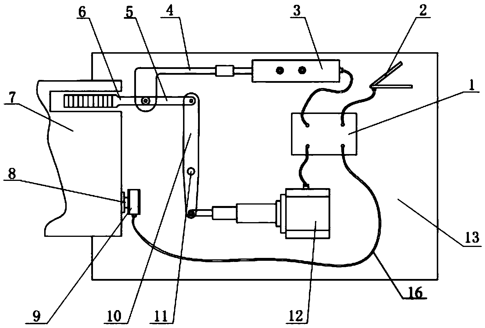
[0030] like figure 1 and figure 2 As shown, the present invention provides a diesel engine speed regulating device, comprising:

[0031] The casing includes an outer casing 13 and a front cover for closing the outer casing 13 .

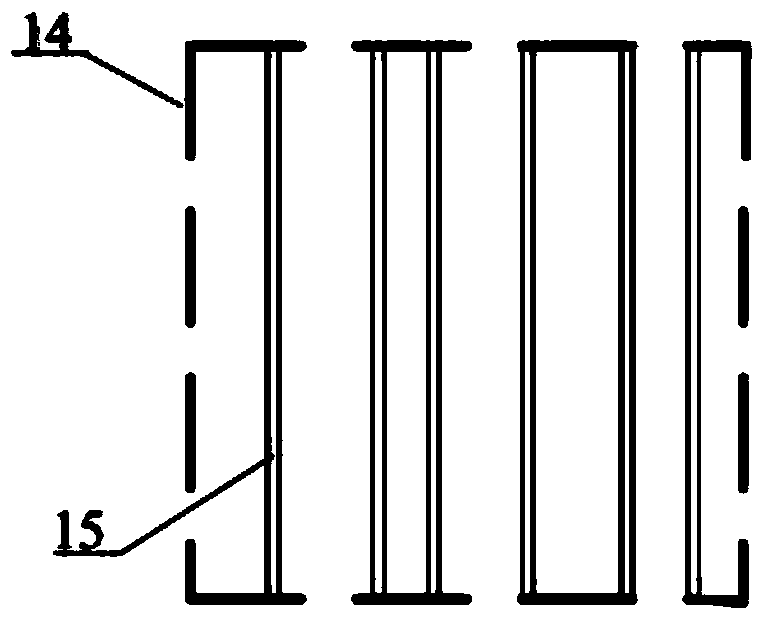
[0032] The inner casing 14 is arranged on the front cover and is closed by the front cover. The inner casing 14 is a breathable mesh casing, and a plurality of test lines 15 are arranged in the inner casing 14 .

[0033] The microprocessor 1 is arranged in the housing 13; in one embodiment, the microprocessor 1 is a single-chip microcomputer control board.

[0034] A linear drive mechanism 12 is arranged in the housing, and the linear drive mechanism 12 is connected to the microprocessor 1 through a wire 16; in one embodiment, the linear drive me...


PUM


Abstract

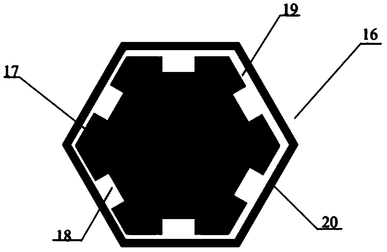
The invention discloses a diesel engine speed control device, comprising a shell, an inner shell, a microprocessor, a linear driving mechanism, a fuel injection pump, a transmission part and a signal collection part, wherein the shell comprises an outer shell and a front cover; the inner shell which is a breathable netty shell is arranged on the front cover, and a plurality of test wires are arranged in the inner shell; the linear driving mechanism is connected to the microprocessor by a wire; the transmission part comprises a first connecting rod, a second connecting rod and a third connecting rod, the first connecting rod is fixed to the shell, one end of the first connecting rod is hinged to the linear driving mechanism while the other end is hinged to the other end of the second connecting rod, one end of the second connecting rod is hinged to the fuel pump ratch of the fuel injection pump, and the third connecting rod is hinged to the second connecting rod; the signal collection part is connected to the microprocessor by a wire; the wire has the same material with the test wires, the wire and the test wires are respectively include an aluminum core the surface of which is provided with a plurality of grooves along the axial direction, refined copper with purity of more than 99.97% is arranged in the grooves, and the outer part of each aluminum core is also sequentially covered with a refined copper film layer and a grapheme layer.

Description

technical field [0001] The invention relates to the technical field of diesel engine accessories, in particular to a diesel engine speed regulating device. Background technique [0002] Existing mechanical diesel engine governors have some disadvantages. During the speed regulation process, it is difficult for the flying block system and spring of the mechanical governor to precisely cooperate with the fuel injection pump, which makes the fuel injection quantity inaccurate and the response speed is slow, which makes the diesel engine under load. When the difference is large, the speed and torque change greatly, and the inaccurate fuel injection quantity may cause insufficient combustion, thereby wasting fuel. However, during the use of general wires, such as when used in harsh conditions such as humid environments, the exposed wires are easily damaged, resulting in short circuits and other faults. Regular maintenance is usually required to avoid accidents and the operation ...

Claims


Application Information

Patent Timeline
Patent Type & Authority Applications(China)
IPC IPC(8): F02D1/02
Inventor 张更娥鞠成伟禤旭旸
Owner NANNING UNIV
Learn More