Vacuum coating gas source quick-changing device

A technology of vacuum coating and gas source, applied in the installation device of container structure, fixed capacity gas storage tank, gas/liquid distribution and storage, etc., can solve the problems of difficulty, high cost, inconvenient replacement of gas source, etc., and achieve deformation Uniform, improve the effect of sealing effect

Active Publication Date: 2021-12-03
LASER FUSION RES CENT CHINA ACAD OF ENG PHYSICS
View PDF6 Cites 0 Cited by
  • Summary
  • Abstract
  • Description
  • Claims
  • Application Information

AI Technical Summary

Problems solved by technology

[0004] The present invention provides a vacuum coating gas source quick-change device, which solves the problem of high cost and difficulty in making the existing gas source device through Kovar sealing technology, and The problem that it is not convenient to replace the air source

Method used


Image

  • Vacuum coating gas source quick-changing device

Examples


Embodiment Construction

[0020] The present invention will be further described below in conjunction with the accompanying drawings.

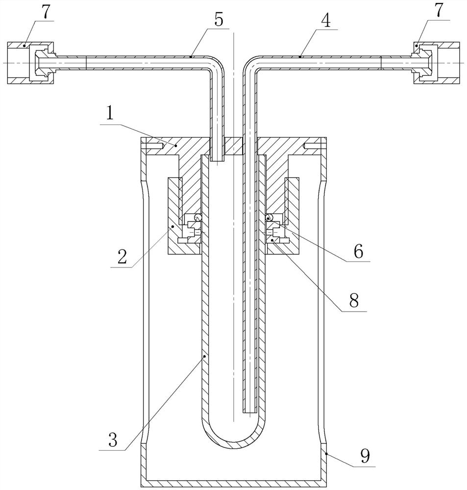
[0021] like figure 1 As shown, the vacuum coating gas source quick change device of the present invention includes a support 1 , a compression nut 2 , a gas storage bottle 3 , an air inlet pipe 4 and an air outlet pipe 5 . The support 1 is made of metal material to facilitate sealing and welding with the air inlet pipe 4 and the air outlet pipe 5. For example, the support 1 is made of stainless steel. The support 1 is cylindrical or includes a cylindrical part, and a circular counterbore is arranged at the center of one bottom surface of the cylinder, figure 1 Among them, the surface directly in contact with the sealing ring 6 is the bottom surface of the support 1, and the center line of the cylinder coincides with the center line of the circular counterbore. For example, the support 1 is in the shape of π or Π on the section passing through the center line of the c...


PUM


Abstract

The invention discloses a vacuum coating gas source quick-changing device, belongs to the field of vacuum coating, and solves the problems of high cost, high difficulty and inconvenience in gas source replacement due to the fact that an existing gas source device is manufactured through a kovar sealing technology. According to the technical scheme, the vacuum coating gas source quick-changing device comprises a support, a gas storage bottle, a gas inlet pipe and a gas outlet pipe, wherein the support is provided with a circular counter bore; the side face of the counter bore is in threaded connection with a compression nut; the gas storage bottle penetrates through the compression nut; a bottle opening is located in the circular counter bore and is fastened through the compression nut; a sealing ring is arranged among the gas storage bottle, the support and the compression nut; two through holes are formed in the bottom of the circular counter bore; and the gas inlet pipe and the gas outlet pipe are arranged in the through holes, welded to the support in a sealed mode and connected with a carrier gas connector in a sealed mode. According to the vacuum coating gas source quick-changing device provided by the invention, metal seal welding and detachable threaded connection are adopted, and a gas source is sealed through the sealing ring, so that kovar sealing is avoided, and the volatile solid and liquid gas source can be rapidly and safely replaced.

Description

technical field [0001] The invention belongs to the technical field of vacuum coating, in particular to a vacuum coating gas source quick change device. Background technique [0002] In modern scientific research and production, multifunctional, low-dimensional thin-film materials have broad application prospects in many fields such as electronics, biology, energy, and chemical industry. Physical vapor deposition and chemical vapor deposition are common methods for preparing multifunctional, low-dimensional thin film materials. The special gas source stored in the gas source storage device is loaded into the deposition chamber through the carrier gas by the bubbling method, and the growth of thin films with different characteristics can be realized during the vapor deposition process. In order to adapt to the characteristics of high strength, large pressure difference and high sealing performance of vacuum coating, most of the gas source devices are made by the Kovar sealin...

Claims


Application Information

Patent Timeline
Patent Type & Authority Applications(China)
IPC IPC(8): F17C3/00F17C13/00
CPCF17C1/00F17C13/002F17C13/06F17C2201/0104F17C2201/032F17C2203/0634F17C2205/0311
Inventor 王涛汪健刘艳松何小珊李俊何智兵
Owner LASER FUSION RES CENT CHINA ACAD OF ENG PHYSICS
Why Eureka
Try Eureka