
A precision axial displacement transmission device

A technology of axial displacement and transmission device, which is applied in the direction of transmission device, belt/chain/gear, mechanical equipment, etc., can solve the problems of axial displacement transmission accuracy limitation, follow-up response, error, etc., to improve the minimum accuracy scale, reduce wear effect

Inactive Publication Date: 2017-01-04
李想
View PDF5 Cites 0 Cited by
  • Summary
  • Abstract
  • Description
  • Claims
  • Application Information

AI Technical Summary

Problems solved by technology

Therefore, the active part rotates once, and the driven part can only move axially at most a few tenths of a millimeter. In order to obtain a small axial displacement, the rotation angle of the active part must be very small. Due to the problems of inertia, static friction and rigidity in the system, the follower cannot follow the response 100%, resulting in errors
In addition, in order to obtain high axial displacement transmission accuracy for the traditional screw nut transmission pair, the screw nut forming the transmission pair must achieve higher machining accuracy. The internal and external thread surfaces of the screw nut must be ground, but the internal thread with a small inner diameter Difficult to grind
Therefore, the improvement of axial displacement transmission accuracy is limited to a certain extent.

Method used


Image

  • A precision axial displacement transmission device
  • A precision axial displacement transmission device
  • A precision axial displacement transmission device

Examples


Embodiment Construction

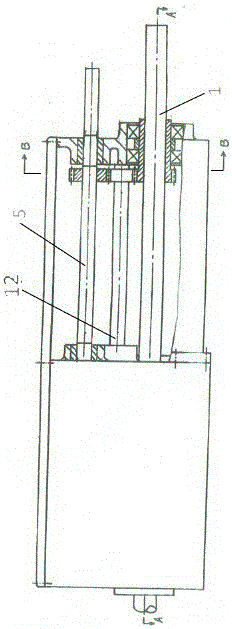
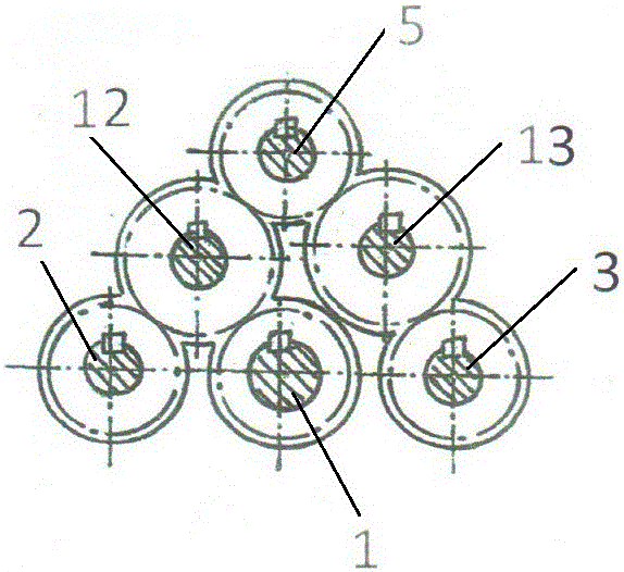
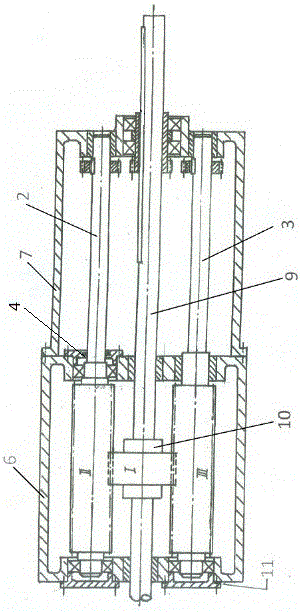
[0028] Such as Figure 1-3 As shown, a precision axial displacement transmission device with a box structure includes a box body, an input shaft 5, a transmission shaft I, a transmission shaft II, and three screw shafts 1, 2, and 3 with coplanar axes to form a parallel meshing Screw transmission pair.

[0029] The box body includes a front box body 6 and a rear box body 7 .

[0030] The input shaft is supported on the upper part of the rear case through a pair of sliding bearings.

[0031] Two transmission shafts are located in the middle part of the rear box body, and the two transmission shafts mesh with the gears on the input shaft respectively through gears, and the two transmission shafts and the input shaft are arranged in parallel.

[0032] The thread transmission pair is located at the lower part of the box body, and the thread transmission pair includes two long-thread screw shafts II and III and one short-thread screw shaft I. Two long-thread screw shafts, one sho...


PUM


Abstract

A precision axial displacement transmission device with a box structure, including a box body, an input shaft, two transmission shafts, and three screw shafts with coplanar axes to form a parallel meshing thread transmission pair, and the three screw shafts are two A long-threaded screw shaft and a short-threaded screw shaft, one of the long-threaded screw shafts is supported in the bearing hole of the front box as a positioning reference for displacement transmission; the second of the long-threaded screw shafts is supported on the front box The bearing hole is used to eliminate the meshing gap; the short-thread screw shaft is a split structure with a taper pin connecting the screw and the mandrel, and the mandrel is supported in the bearing hole of the front box for displacement transmission. Supported on the input shaft on the top of the rear box body, its upper gear drives the gears at the rear ends of the three screw shafts through the gears on the two intermediate transmission shafts, so that the three screw shafts rotate at a differential speed. Compared with the traditional screw nut transmission pair, the invention can greatly improve the minimum accuracy scale of axial displacement.

Description

technical field [0001] The invention relates to a precision axial displacement transmission device, which belongs to a screw transmission pair formed by a new meshing method. Background technique [0002] The traditional mechanical precision axial displacement transmission device mostly adopts the form of screw (screw) and nut. With the current processing methods and the strength requirements for the thread tooth shape, the thread pitch can only be in the order of millimeters to 1 / 10 millimeters . Therefore, the active part rotates once, and the driven part can only move axially at most a few tenths of a millimeter. In order to obtain a small axial displacement, the rotation angle of the active part must be very small. Due to the problems of inertia, static friction and rigidity in the system, the follower cannot follow the response 100%, resulting in errors. In addition, in order to obtain high axial displacement transmission accuracy for the traditional screw nut transmi...

Claims


Application Information

Patent Timeline
Patent Type & Authority Patents(China)
IPC IPC(8): F16H25/24
Inventor 李军李想
Owner 李想
Learn More