
Detection device and detection method for detecting air tightness of air-tight door of nuclear power plant by using constant pressure method

A detection device and air tightness testing technology, which is applied in the direction of liquid tightness measurement using liquid/vacuum degree, and by measuring the increase and deceleration rate of fluid, etc., which can solve the problem of not being able to test the airtightness of the airtight door and affecting the accuracy of the measurement , inaccurate detection methods, etc., to achieve the effect of reducing the amount of testers and manual calculations, reducing gas leakage, and quantitatively calculating the airtightness

Active Publication Date: 2015-01-07
CHINA NUCLEAR IND HUAXING CONSTR
View PDF9 Cites 13 Cited by
  • Summary
  • Abstract
  • Description
  • Claims
  • Application Information

AI Technical Summary

Problems solved by technology

However, this detection method is not accurate: the gas pressure filled into the test box will gradually decrease over time, and the airtightness of the airtight door cannot be tested at a fixed pressure. Therefore, it can only be tested perceptually. It is impossible to quantitatively calculate the tightness of the tested part
[0004] In addition, in addition to the air leakage of the tested part, there is also a gas leak at the connection between the tested part and the detection device, which affects the accuracy of the measurement

Method used


Image

  • Detection device and detection method for detecting air tightness of air-tight door of nuclear power plant by using constant pressure method
  • Detection device and detection method for detecting air tightness of air-tight door of nuclear power plant by using constant pressure method

Examples


Embodiment Construction

[0040] Embodiments of the present invention will be described in further detail below in conjunction with the accompanying drawings.

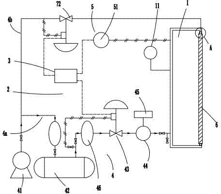
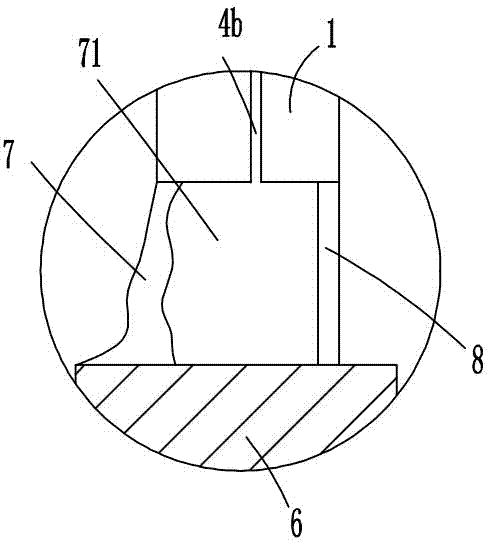
[0041] Figure 1 to Figure 2 Shown is the structural representation of the present invention.

[0042] The reference signs are: air tightness test box 1, U-shaped meter 11, test system 2, digital regulator 3, high-pressure air supply device 4, first pipeline 4a, second pipeline 4b, air compressor 41, Gas buffer tank 42, pneumatic regulating valve 43, gas mass flowmeter 44, flow totalizer 45, filter type pressure reducing valve 46, box state monitoring device 5, pressure transmitter 51, test piece 6, sealing ring 7. Inflatable cavity 71 , pressure control valve 72 , sealing ring 8 .

[0043] Such as Figure 1 to Figure 2 as shown,

[0044]A testing device for testing the airtightness of an airtight door in a nuclear power plant by the constant pressure method, including an airtightness test box 1 and a test system 2, the airtightness test bo...


PUM


Abstract

The invention discloses a detection device for detecting air tightness of an air-tight door of a nuclear power plant by using a constant pressure method. The detection device comprises an air tightness testing box body and a testing system, wherein a testing opening is formed in the air tightness testing box body; a tested part is arranged on the testing opening; the testing system comprises a digital adjuster; a flexible sealing glue ring is cast between the testing opening and the tested part; an air inflation cavity is defined by a sealing ring, the testing opening, the tested part and the sealing glue ring jointly; the digital adjuster is used for adjusting the opening of a pneumatic adjusting valve and the opening of an inflation control valve according to the air pressure tested by a pressure transmitter to enable the air pressure inside the air tightness testing box body to be equal to the designed pressure intensity of the tested part and enable the air pressure inside the air inflation cavity to be approximate to that inside the air tightness testing box body. The detection device has the advantages that the structure is simple, the use is convenient, the automation degree is high, the air tightness of the tested part can be calculated quantitatively, and the leakage of non-testing gases is reduced.

Description

technical field [0001] The invention relates to the technical field of airtight door detection, in particular to the detection of airtightness of an airtight door of a nuclear power plant, specifically a detection device and a detection method for detecting the airtightness of an airtight door of a nuclear power plant by a constant pressure method. Background technique [0002] In order to ensure the normal operation of the nuclear power plant units, the airtightness of the airtight doors of the nuclear power plants under construction in my country needs to be strictly tested before they can be put into use. The airtight tests are all carried out abroad. For the domestically produced nuclear power airtight door airtight test project, to verify whether the airtight performance of the airtight door meets the design requirements of nuclear power, the matching airtight test device technology is still At present, there is no device suitable for the airtightness test of the airtight...

Claims


Application Information

Patent Timeline
IPC IPC(8): G01M3/26
Inventor 毛家驹冯丽琴江涛王永
Owner CHINA NUCLEAR IND HUAXING CONSTR
Learn More