
Self-adaptive measuring device for polarization parameter of radar electromagnetic signal

A polarization parameter and electromagnetic signal technology, applied in radio wave measurement systems, instruments, etc., can solve problems such as complex structure of measurement devices, and achieve the effects of easy engineering implementation, simple structure, and low development/maintenance costs

Active Publication Date: 2015-01-07
UNIT 63892 OF PLA
View PDF5 Cites 13 Cited by
  • Summary
  • Abstract
  • Description
  • Claims
  • Application Information

AI Technical Summary

Problems solved by technology

[0006] Aiming at the problem that the existing polarization measurement technology cannot adapt to the rapid change of polarization parameters and the structure of the measurement device is complex, the present invention provides a polarization parameter adaptive measurement method and device for radar electromagnetic signals. Compared with other measurement methods, Since the adaptive polarization measurement method uses the vector sum and vector difference of the orthogonal polarization components of the electromagnetic signal to satisfy a specific amplitude and phase relationship, and then uses a local minimum search algorithm to measure the polarization parameters

Method used


Image

  • Self-adaptive measuring device for polarization parameter of radar electromagnetic signal
  • Self-adaptive measuring device for polarization parameter of radar electromagnetic signal
  • Self-adaptive measuring device for polarization parameter of radar electromagnetic signal

Examples


Embodiment Construction

[0014] The present invention will be further described below in conjunction with the accompanying drawings and specific implementation.

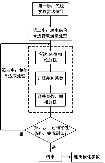
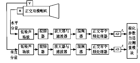
[0015] figure 1 It is a basic flowchart of the adaptive polarization measurement principle of the technical solution of the present invention. As shown in the figure, the present invention includes four processing steps. The orthogonal dual-mode horn dual-polarization antenna receives the radar signal, performs amplification, filtering, frequency mixing and intermediate frequency processing through two channels, and then feeds polarization parameters and differential self- Adapt to the measurement module, and finally measure the polarization parameters of the radar signal by observing whether the adaptive tracking condition of zero value or minimum value is satisfied. The following are the detailed steps of the technical solution of the present invention.

[0016] In the first step, the dual-polarized antenna receives the radar electromagn...


PUM


Abstract

The invention relates to the technical field of electromagnetic wave self-adaptive measurement and discloses a self-adaptive measuring device for a polarization parameter of a radar electromagnetic signal. The device comprises orthogonal bimodule horn dual polarized antennas, a binary-channel signal processing module and a polarization parameter self-adaptive measuring module. The orthogonal bimodule horn dual polarized antennas of the same caliber are connected with the input end of the binary-channel signal processing module through a horizontal polarization component and a vertical polarization component cable respectively, and the output end of the binary-channel signal processing module is connected with the polarization parameter self-adaptive measuring module through the horizontal polarization component and the vertical polarization component cable respectively. By means of the self-adaptive measuring device for the polarization parameter of the radar electromagnetic signal, a radar signal is received through the orthogonal bimodule horn dual polarized antennas, processed through the binary-channel signal processing module and then fed into a polarization parameter and difference self-adaptive measuring module, and finally, the polarization parameter of the radar signal can be measured by observing whether the self-adaptive tracking condition of a zero value or a minimum value is met. The self-adaptive measuring device is low in cost and easy to achieve.

Description

technical field [0001] The invention relates to the technical field of self-adaptive measurement of electromagnetic waves, in particular, using the inherent polarization characteristics of electromagnetic waves, adopting vector sum-difference processing for the horizontal polarization components and vertical polarization components of received electromagnetic signals, so as to realize the polarization of electromagnetic signals. A polarization parameter adaptive measurement method and device for radar electromagnetic signals at instantaneous polarization parameters. Background technique [0002] Radar signals, optical signals and other electromagnetic wave signals have polarization characteristics. For example, during the working process of the radar, the electromagnetic wave signal is transmitted to the target, and the target information is obtained by comparing the difference between the target echo signal and the transmitted signal in the time domain, frequency domain, an...

Claims


Application Information

Patent Timeline
Patent Type & Authority Applications(China)
IPC IPC(8): G01S7/40
CPCG01S7/40
Inventor 戴幻尧孔德培周波莫翠琼刘文钊陈秋菊刘勇朱健东赵晶崔建岭
Owner UNIT 63892 OF PLA
Learn More