
Parallel transmission structure automatic leveling mechanism

A transmission structure and automatic leveling technology, applied in non-electric variable control, control/adjustment systems, instruments, etc., can solve the problems of long time consumption, high labor intensity of staff, large error in measurement results, etc., and achieve short adjustment time, The effect of simple structure and highly automated precise positioning control

Active Publication Date: 2017-01-11
黑龙江科大科技开发有限公司
View PDF5 Cites 0 Cited by
  • Summary
  • Abstract
  • Description
  • Claims
  • Application Information

AI Technical Summary

Problems solved by technology

[0005] The purpose of the present invention is to provide an automatic leveling mechanism of a parallel transmission structure to solve the problem of precise positioning of the Z-axis direction of equipment such as CNC machine tools, CNC engraving machines and 3D printers by manual adjustment. The problem of high labor intensity and large error in measurement results

Method used


Image

  • Parallel transmission structure automatic leveling mechanism

Examples


Embodiment Construction

[0014] The present invention will be further described in detail below in conjunction with the accompanying drawings.

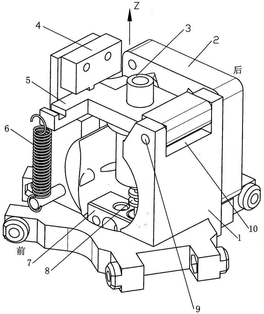
[0015] Such as figure 1 As shown, the automatic leveling mechanism of the parallel transmission structure includes a parallel support 1, a nozzle fixing seat 3, a heating block 7, and a nozzle 8. The upper end and the lower end of the parallel support 1 are connected, and the heating block 7 is arranged in the parallel support 1 The lower part of the nozzle 8 is fixed in the nozzle installation hole of the heating block 7, and the lower end of the nozzle 8 extends out of the nozzle installation hole of the heating block 7, and the lower end of the nozzle 8 protrudes from the nozzle installation hole of the heating block 7 by 3-5 mm, and the upper end of the nozzle 8 is fixed to the nozzle The seat 3 is fixedly connected, and the hot end assembly is composed of the heating block 7, the nozzle 8 and the nozzle fixing seat 3. The automatic leveling mechanism of ...


PUM


Abstract

The invention provides an automatic leveling mechanism for a parallel transmission structure and belongs to the technical field of automatic precision adjustment. The automatic leveling mechanism aims to solve the problems that when a numerically-controlled machine tool, a numerically-controlled carving machine, a 3D printer and other devices are positioned accurately in the Z-axis direction through manual adjustment, consumed time is long, the labor intensity is high and the error of a measuring result is large in the adjusting process. A heating block is arranged in a parallel connection support. The lower end of a spray head stretches out of a spray head mounting hole in the heating block. The upper end of the spray head is fixedly connected with a spray head fixing base. The upper end of the spray head fixing base fixedly penetrates out of a through hole of a hot end assembly fixing frame. One end of the hot end assembly fixing frame is hinged to the parallel connection support. A microswitch is fixedly connected with the parallel connection support. The microswitch is located over the other end of the hot end assembly fixing frame. A gap is formed between the microswitch and the hot end assembly fixing frame. The hot end assembly fixing frame is connected with the bottom of the parallel connection support through an elastic extension mechanism. The automatic leveling mechanism is mainly applied to the numerically-controlled machine tool, the numerically-controlled carving machine, the 3D printer, a sorting system and the like.

Description

technical field [0001] The invention relates to an automatic leveling mechanism of a transmission structure, which belongs to the technical field of automatic precision adjustment. Background technique [0002] Automatic leveling mechanisms have been widely used in many modern equipment. Before the equipment works, it is necessary to set the height reference of the working head when it is working, that is, the zero point of the Z-axis coordinate system. The working head moves downward in the height direction (Z-axis direction), and slowly approaches the working platform or the automatic leveling component. When the working head touches the working plane and a certain amount of displacement occurs, the micro switch is triggered. The signal is sent to the controller to calculate the actual height value of the point, and so on, measure the rest of the workbench, so as to calculate the actual height of each point, and modify and correct it in the actual work process, so as to a...

Claims


Application Information

Patent Timeline
Patent Type & Authority Patents(China)
IPC IPC(8): G05D3/00
Inventor 张海录李洪涛邵凯轩
Owner 黑龙江科大科技开发有限公司
Learn More