
Universal timer based on embedded operating system and working method of universal timer

An operating system and timer technology, applied in the direction of program startup/switching, multi-program device, etc., can solve the problem of different timer function methods and interface functions, increase the cost of product upgrade and maintenance, and affect product stability and reliability and other issues to achieve the effect of facilitating hierarchical and modular design, ensuring real-time requirements, and improving CPU efficiency and performance

Inactive Publication Date: 2015-01-07
TIANJIN KEYVIA ELECTRIC CO LTD
View PDF4 Cites 2 Cited by
  • Summary
  • Abstract
  • Description
  • Claims
  • Application Information

AI Technical Summary

Problems solved by technology

However, there are differences in the design ideas and standards of each embedded operating system, resulting in different timer function methods and interface functions.
Due to the upgrade or change of the operating system, the user application program needs to be constantly changed to adapt to the change of the timer interface, which increases the cost of product upgrade and maintenance, and affects the stability and reliability of the product
[0003] In addition, for embedded operating systems, a tick-based scheduling mechanism is generally adopted. Tick is the minimum time unit of the embedded operating system; according to system design characteristics and requirements, the time unit of tick is generally in the range of 5ms~20ms; the tick value is too small , task scheduling is too frequent, the CPU system overhead caused by task context switching is large, and the efficiency of the entire system is greatly reduced; and the tick is too large, the real-time performance of the system will be reduced
In some strong real-time systems, for timing functions that require high precision, such as 1ms software timing functions, general embedded operating system timers cannot meet the requirements.

Method used

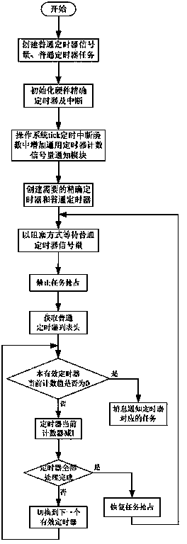

Image

  • Universal timer based on embedded operating system and working method of universal timer
  • Universal timer based on embedded operating system and working method of universal timer

Examples


Embodiment Construction

[0018] The present invention will be described in detail below with reference to the accompanying drawings and embodiments.

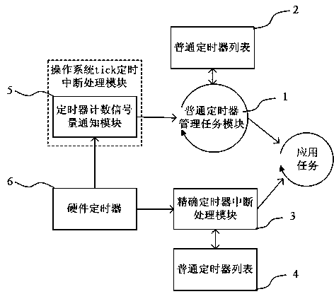
[0019] Such as figure 1 As shown, a general-purpose timer based on an embedded operating system includes an ordinary timer management task module 1, an ordinary timer list 2, an accurate timer interrupt processing module 3, an accurate timer list 4, and timer counting semaphore notification Module 5 and hardware timer 6;

[0020] ① The common timing management task module 1 is responsible for the timing management of all common timers. After receiving the notification sent by the timer counting semaphore notification module each time, it starts to scan the entire common timer list. Once a certain timing is found When the timer time is up, the application task associated with the timer is notified through a message.

[0021] ② The general timer list 2 described above records all general timer information, including: timer count threshold, timer count c...


PUM


Abstract

The invention discloses a universal timer based on an embedded operating system and a working method of the universal timer. The universal timer comprises a common timer management task module, a common timer list, a precise timer interrupt processing module, a precise timer list, a timer counting semaphore informing module and a hardware timer. The method includes controlling the executing frequency of an application program by the aid of the hardware timer according to different set values of a common timer and a precise timer. The universal timer has the advantages that by the aid of universal technology of the embedded operating system, functions of the universal timer are finished, an application crossing operating systems is realized, a common timing function based on a tick unit and an accurate timing function based on a 1ms unit can be realized according to application requirements, the efficiency and the performance of a CPU (central processing unit) is improved when a system function is ensured, the system is optimized, and real-time requirements of the system are met.

Description

technical field [0001] The invention belongs to an embedded operating system timer, in particular to a general-purpose timer based on an embedded operating system and a working method thereof. Background technique [0002] In the field of embedded product development and application, the embedded operating system is the technical basis of the entire software product. The functions of embedded products are generally executed in a cycle, and the task design is also based on this principle. Therefore, each embedded operating system provides flexible and diverse software timer function modules for the convenience of users. However, there are differences in the design ideas and standards of each embedded operating system, resulting in different timer function methods and interface functions. As a result, due to the upgrade or change of the operating system, the user application program needs to be constantly changed to adapt to the change of the timer interface, thereby increas...

Claims


Application Information

Patent Timeline
IPC IPC(8): G06F9/48
Inventor 曾庆钊李政吴苏卓
Owner TIANJIN KEYVIA ELECTRIC CO LTD
Learn More