Control switch for increased operational safety

A technology to increase operation and control switches, which is applied in the direction of electric switches, electrical components, emergency actuators, etc., can solve the problems of switch jamming, leakage, and unguaranteed service life of switches, and achieve rapid return and guaranteed service life Effect

A technology to increase operation and control switches, which is applied in the direction of electric switches, electrical components, emergency actuators, etc., can solve the problems of switch jamming, leakage, and unguaranteed service life of switches, and achieve rapid return and guaranteed service life Effect

CN104269302BInactive Publication Date: 2016-05-25CHENGDU RUIYI INFORMATION TECH

Image

  • Control switch for increased operational safety

Examples


Embodiment 1

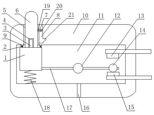
[0011] like figure 1 As shown in the figure, the control switch capable of increasing the operational safety includes a housing 10 with a cavity 11 provided therein, a through hole 5 is provided on the housing 10, and the through hole 5 communicates with the interior of the housing 10, and the cavity 11 There is a limit bump 1 in the middle, a push button 6 is fixed on the top of the limit bump 1, and the push button 6 can rotate along its own axis on the limit bump 1, and the push button 6 passes through the through hole. Hole 5, the side wall of the through hole 5 is concave to form a strip groove 8, and the strip groove 8 is communicated with the top of the through hole 5, the bottom surface of the strip groove 8 is concave to form a clamping groove 21, and the clamping groove 21 The depth is greater than the depth of the strip groove 8, and a smooth connection is formed between the side wall of the clamping groove 21 and the strip groove 8. The side wall of the push button...


PUM


Abstract

The invention discloses a control structure capable of improving the operating safety. A through hole is formed in a shell, a limiting convex block is arranged in a cavity, a pressing button is fixed to the limiting convex block and penetrates through the through hole, the through hole sinks inwards to form a strip-shaped groove, the strip-shaped groove sinks inwards to form a clamping groove, the pressing button is provided with a limiting shaft, the limiting shaft is provided with a telescopic shaft, and a telescopic spring is connected with the telescopic shaft; the limiting convex block is provided with a main spring, the main spring is connected with the limiting convex block and the cavity, the limiting convex block is provided with a connecting rod, the connecting rod is fixed to the limiting convex block and provided with a rotating shaft, the rotating shaft is fixed to the shell, the connecting rod is provided with a metal contact ball, a normally-open contact and a normally-closed contact are arranged in the cavity, and the metal contact ball is arranged between the normally-open contact and the normally-closed contact. According to the control structure, returning is achieved through springs arranged in a plurality of positions, the returning speed is high, the phenomenon that the control structure is struck is avoided, and an operator can use the control structure more safely.

Description

technical field [0001] The present invention relates to a switch, in particular to a control switch capable of increasing operational safety. Background technique [0002] A switch is an electronic component that can open a circuit, interrupt current, or cause it to flow to other circuits. Switching power supply is a power supply that uses modern power electronic technology to control the time ratio of switching on and off to maintain a stable output voltage. Compared with switching power supply and linear power supply, the cost of both increases with the increase of output power, but the growth rate of both is different. The cost of the linear power supply is higher than that of the switching power supply at a certain output power point, which is called the cost reversal point. With the development and innovation of power electronic technology, switching power supply technology is also constantly innovating, and this cost reversal point is increasingly moving to the low o...

Claims


Application Information

Patent Timeline
25 May 2016
Publication
CN104269302B
IPC
H01H13/14; H01H13/20; H01H13/26
CPC
H01H13/26; H01H13/56; H01H2221/016; H01H2231/002
Inventors
任佳; 袁祖斌