Re-closure transmission mechanism with clutching function in circuit breaker re-closure device

A transmission mechanism and reclosing technology, applied in emergency protection devices, contact operating mechanisms, protection switch operation/release mechanisms, etc., can solve the problems of power-on, automatic tripping, and hidden safety hazards of maintenance workers, etc. The effect of small resistance, ensuring the safety of electricity consumption, and ensuring the safety of maintenance

Inactive Publication Date: 2015-01-07
ZHEJIANG MARKARI ELECTRIC +3
View PDF9 Cites 5 Cited by
  • Summary
  • Abstract
  • Description
  • Claims
  • Application Information

AI Technical Summary

Problems solved by technology

Although this structure realizes the function of automatic closing, it has the following defects: when the user renews the fee, the threaded sleeve slides, drives the shift fork and the handle to perform the closing action, and the handle of the control mechanism then drives the handle of the circuit breaker clockwise. Rotate to close, but for the prepaid circuit device, when the user owes the fee or the circuit fails, it will automatically trip, and the handle of the circuit breaker will reset counterclockwise, but the electric operating mechanism of the above-mentioned reference document (101707169A) The control handle is always limited behind the handle of the circuit breaker, causing the handle of the circuit breaker to fail to turn and trip
[0005] When the automatic closing device of this structure is used in conjunction with the circuit breaker, if the remote control terminal misoperates when it is necessary to perform on-site maintenance on the energized line, it will send a drive signal to the forward and reverse motor to make the automatic closing device close again. action, and drive the circuit breaker to close, which will cause the maintenance line to be energized, which will cause great hidden dangers to the life safety of the maintenance workers

Method used


Image

  • Re-closure transmission mechanism with clutching function in circuit breaker re-closure device
  • Re-closure transmission mechanism with clutching function in circuit breaker re-closure device
  • Re-closure transmission mechanism with clutching function in circuit breaker re-closure device

Examples


Embodiment Construction

[0025] The following specific descriptions of the present invention are given by the examples, which are only used to further illustrate the present invention, and should not be construed as limiting the protection scope of the present invention.

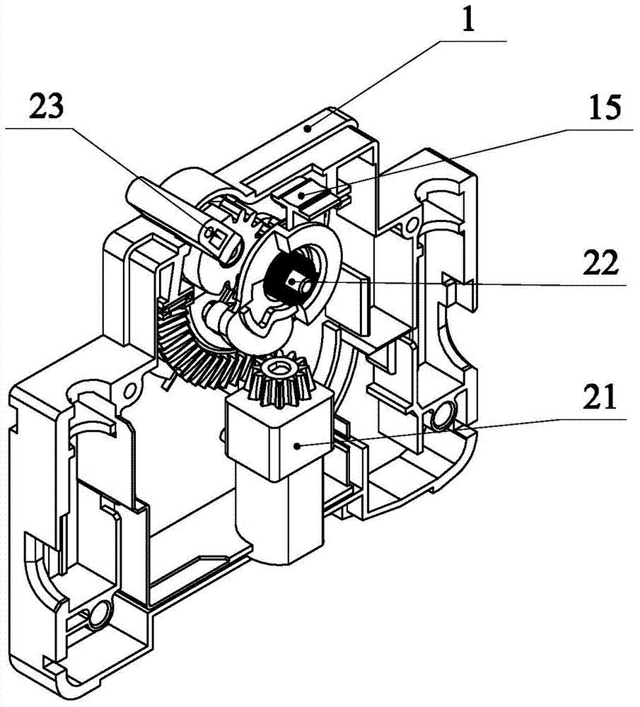
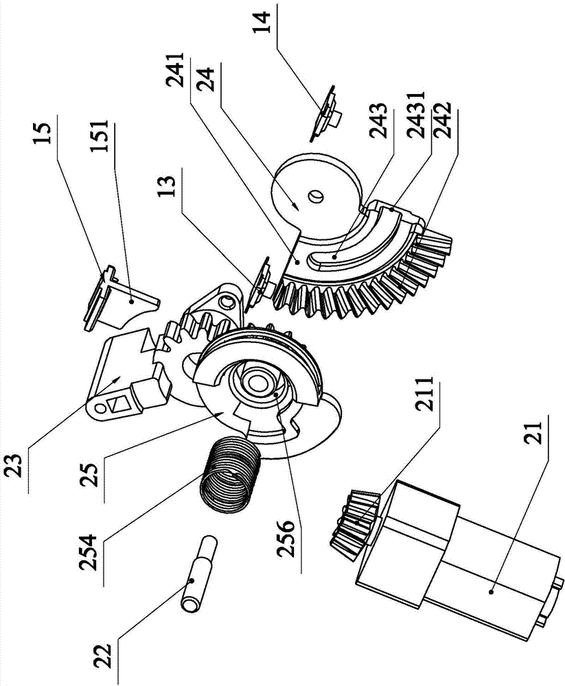
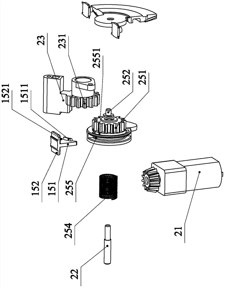
[0026] Such as Figure 1-5 Specific embodiments of the invention shown, such as Figure 1-3The specific embodiment of the present invention shown includes a housing 1, a forward and reverse motor 21 arranged in the housing, a main shaft 22, and a drive handle 23 for driving the handle linkage of the circuit breaker. A transmission piece 24 and a transmission member 25 are provided for rotation, and the forward and reverse motor 21 is driven and coupled with the transmission piece 24. The transmission piece 24 described in this embodiment includes a fan-shaped portion 241, and the center of the fan-shaped portion is located at the On the center line of the main shaft 22, the arc-shaped outer edge of the fan-shaped part 241 is pr...


PUM


Abstract

The invention discloses a re-closure transmission mechanism with the clutching function in a circuit breaker re-closure device. The re-closure transmission mechanism comprises a shell, a forward and reverse rotation motor, a main shaft and a driving handle, wherein the forward and reverse rotation motor and the main shaft are arranged inside the shell, and the driving handle is used for driving linkage of a handle of a circuit breaker. A transmission piece and a transmission part are arranged on the main shaft in a rotating mode. A clutching sliding block is arranged on the shell in a slippage mode, wherein the axial direction of the main shaft is the same as that of the clutching sliding block. A linkage plate stretching into the shell is arranged at the inner end of the clutching sliding block. The main shaft is axially sleeved with the transmission part in a slippage mode. The linkage plate and the transmission part are in synchronous linkage in the axial direction of the main shaft. The clutching sliding block drives a linkage shaft of the transmission part to be gradually disengaged from an arc groove axially in the slippage process. The re-closure transmission mechanism has the advantages that clutching control can be carried out on linkage between the forward and reverse rotation motor and the driving handle, and therefore safe line repair is ensured.

Description

technical field [0001] The invention relates to a reclosing device of a circuit breaker, in particular to a reclosing transmission mechanism with a clutch function in the reclosing device of a circuit breaker. Background technique [0002] With the development of my country's smart grid, under the premise of requiring the grid to operate safely, it is urgent to control electrical appliances intelligently. For example, the combined use of prepaid energy meters and prepaid miniature circuit breakers (such as MM7S and MM10S series products produced by Zhejiang Mikeli Electric Co., Ltd.) can allow electricity users to automatically cut off the power supply when the prepaid electricity fee is exhausted. This greatly facilitates the distribution and control of electric energy by the power supply unit. However, after the user renews the fee, the user's circuit breaker cannot be automatically closed in time, and the user or the power supply staff need to manually operate, which bri...

Claims


Application Information

Patent Timeline
Patent Type & Authority Applications(China)
IPC IPC(8): H01H71/70
CPCH01H3/58H01H71/1009H01H71/70
Inventor 李敏杨志国张延华张培夫蔡胜利占玉兵顾斌斌
Owner ZHEJIANG MARKARI ELECTRIC
Why Eureka
Try Eureka