A vehicle track changing device

A technology for locomotives and carriages, applied in the field of on-board rail changing devices for railway engineering vehicles, which can solve the problems of high labor intensity for operators, inability to operate flat cars, and high maintenance costs, and achieve the effects of reasonable design structure, rapid replacement, and maintenance safety

Active Publication Date: 2017-03-08
GEMAC ENG MACHINERY
View PDF5 Cites 0 Cited by
  • Summary
  • Abstract
  • Description
  • Claims
  • Application Information

AI Technical Summary

Problems solved by technology

The maintenance cost is high, the labor intensity of the operators is high, and there are unsafe factors; in addition, due to the problem of speed and axle load, the current flat car cannot run on the high-speed rail line

Method used


Image

  • A vehicle track changing device
  • A vehicle track changing device
  • A vehicle track changing device

Examples


Embodiment Construction

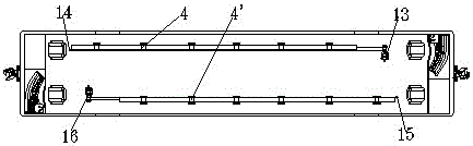
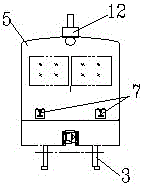
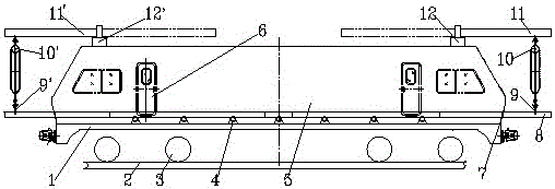
[0018] given in the present invention figure 1 , figure 2 , image 3 In the shown embodiment, the locomotive car 5 is installed and fixed on the locomotive chassis 1, and the power unit is installed on the locomotive chassis 1 (in the car), and the wheelset 3 installed under the locomotive chassis 1 is located on the track 2, and the two ends of the car are respectively A cab and a locomotive control mechanism are provided, and doors 6 are respectively provided on the front and rear sides of the compartment; the first row of guide wheel devices 4 and the second row of guide wheel devices 4' with the same structure are respectively provided on both sides of the locomotive chassis 1 in the compartment; On the car body of the front of the first row of guide wheel devices 4 and the two ends of the second row of guide wheel devices 4', rail inlets and outlets 7 are respectively provided; On the first row of guide wheel devices 4 and the second row of guide wheel devices 4'.

[...


PUM


Abstract

A vehicle-mounted rail replacing device is characterized in that a power device is mounted on a locomotive chassis; a wheel set mounted under the locomotive chassis lies on a track; a cab and a locomotive control mechanism are arranged at the two ends of a carriage, respectively; a first row of guide wheel device and a second row of guide wheel device are arranged on the two sides of the locomotive chassis, respectively, wherein the structures of the first row of guide wheel device and the second row of guide wheel device are as same as each other; steel rail exits are formed in the two ends of a locomotive, respectively; a first suspension arm seat and a second suspension arm seat are arranged at the tops of the two ends of the locomotive, respectively; a first suspension arm and a second suspension arm are inserted in holes in the first suspension arm seat and the second suspension arm seat; a first hand-drive block and a second hand-drive block are suspended on suspension rings at one ends of the first suspension arm and the second suspension arm; first rail-clamping pliers and second rail-clamping pliers are mounted at the lower ends of the hand-drive blocks, respectively; and a pulley and a winch are mounted on a carriage chassis, respectively. Power is provided to the rail replacing device through a vehicle-mounted hydraulic system and an electric system; a steel wire rope on the winch is enabled to act through operating a control device; and steel rails are conveyed out or conveyed in from the exits in the two ends of the carriage under the cooperation of the hand-drive blocks and the rail-clamping pliers.

Description

technical field [0001] The invention relates to a vehicle-mounted rail changing device, in particular to a vehicle-mounted rail changing device for railway engineering vehicles. Background technique [0002] At present, in railway track maintenance, the equipment used to replace rails on the line is usually rail receiving cars and overhaul trains. It is the replacement of a small section of rails. The specific construction method is to use a rail car to pull a flat car, transport one or two rails to the destination, manually unload the new rails on the line for rail replacement, and lift the replaced old rails to the flat. Car back. The maintenance cost is high, the labor intensity of the operators is high, and there are unsafe factors; in addition, due to the speed and axle load problems, the current flat car cannot run on the high-speed rail line. The above situation determines the need for a more convenient vehicle-mounted rail changing device for routine maintenance of...

Claims


Application Information

Patent Timeline
Patent Type & Authority Patents(China)
IPC IPC(8): E01B29/16
CPCE01B29/16E01B2203/141
Inventor 陈斌张亚军贾晓侠刘建书李玮
Owner GEMAC ENG MACHINERY
Why Eureka
Try Eureka