Three-phase H-bridge driving system for open type winding induction motor
An open-winding, induction motor technology, applied in control systems, AC motor control, electrical components, etc., can solve problems such as complex dual-inverter modulation algorithms, simplify modulation strategies, suppress system zero-sequence current, and improve system performance. The effect of running performance
- Summary
- Abstract
- Description
- Claims
- Application Information
AI Technical Summary
Problems solved by technology
Method used
Image
Examples
specific Embodiment approach 1
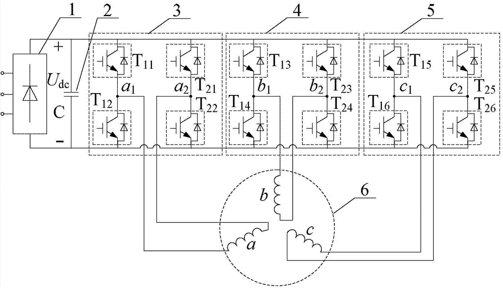
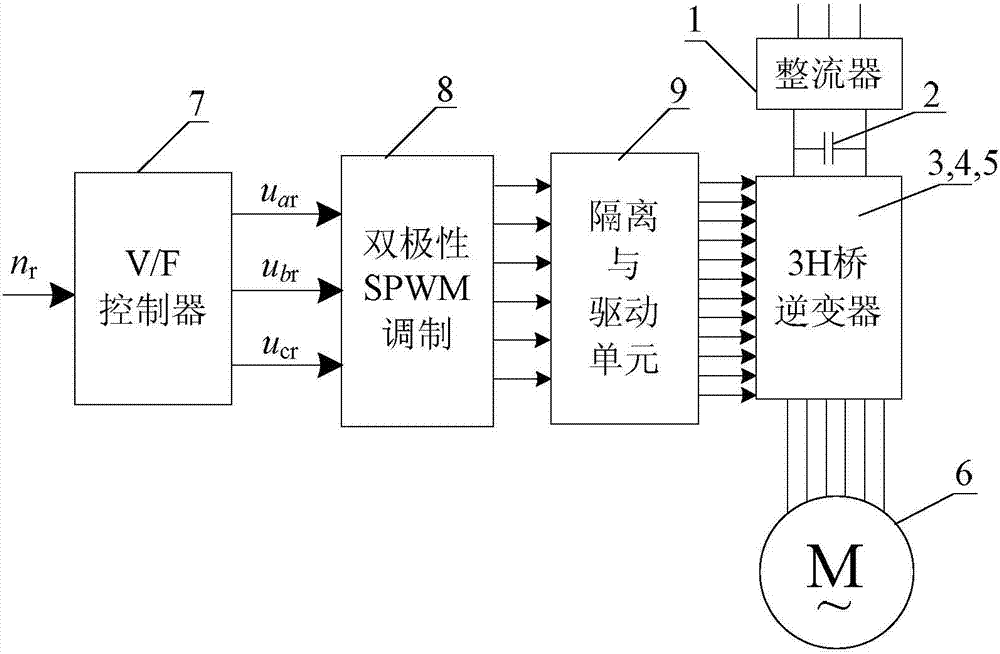
[0014] Specific implementation mode one: the following combination figure 1 with figure 2 Describe this embodiment, the drive controller of the open winding induction motor 3H bridge drive system described in this embodiment, it includes a rectifier 1, a DC filter capacitor 2, a 3H bridge inverter, a V / F controller 7, a bipolar SPWM modulation 8 and isolation and drive unit 9; 3 H-bridge inverter is composed of A-phase H-bridge inverter 3, B-phase H-bridge inverter 4 and C-phase H-bridge inverter 5;
[0015] A DC filter capacitor 2, an A-phase H-bridge inverter 3, a B-phase H-bridge inverter 4, and a C-phase H-bridge inverter 5 are sequentially connected in parallel on the DC bus output by the rectifier 1;
[0016] The A-phase winding of the open-winding induction motor 6 is connected in parallel between the two AC output terminals of the A-phase H-bridge inverter 3;
[0017] The B-phase winding of the open-winding induction motor 6 is connected in parallel between the two ...
specific Embodiment approach 2
[0026] Specific implementation mode two: the following combination Figure 3 to Figure 5 Describe this embodiment mode, this embodiment mode is further explained to embodiment mode 1, the control of bipolar SPWM modulation 8 pairs of 3H bridge inverters is realized by DSP digitally, and the control process is:
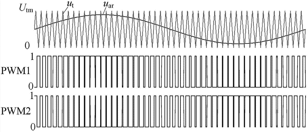
[0027] V / F controller 7 according to the speed command n r Calculate the amplitude and frequency of the voltage required by the motor, and then generate three-phase symmetrical sinusoidal modulation waves u ar , u br , u cr ; The timer T1 of DSP is used to produce the triangular carrier of fixed amplitude and frequency; The three-phase sinusoidal modulation wave is compared with the triangular carrier to generate 6 PWM switching signals.
[0028] image 3 It is the a-phase bipolar SPWM modulation waveform of the present invention. By sinusoidally modulating the wave u in the DSP ar Generate triangular wave u with timer T1 t The comparison of two channels of comp...
specific Embodiment approach 3
[0031] Specific implementation mode three: this implementation mode will further explain the first embodiment mode, the V / F controller 7 according to the speed command n r Calculate the amplitude and frequency of the voltage required by the motor, and then generate three-phase symmetrical sinusoidal modulation waves u ar , u br , u cr The process is:
[0032] First, according to the speed command n r and motor rated slip s N Calculate the synchronous speed n s :
[0033] n s = n r 1 - s N ;
[0034] Second, the synchronous speed n s Converted to motor stator current frequency f 1 :
[0035] In the formula, p is the number of pole pairs of the motor;
[0036] Then, according to the constraints of the induction motor voltage and frequency, calculate at frequency ...
PUM
 Abstract
Description
Claims
Application Information
 - R&D
- Intellectual Property
- Life Sciences
- Materials
- Tech Scout
- Unparalleled Data Quality
- Higher Quality Content
- 60% Fewer Hallucinations
Browse by: Latest US Patents, China's latest patents, Technical Efficacy Thesaurus, Application Domain, Technology Topic, Popular Technical Reports.
© 2025 PatSnap. All rights reserved.Legal|Privacy policy|Modern Slavery Act Transparency Statement|Sitemap|About US| Contact US: help@patsnap.com


