3h Bridge Drive System of Open Winding Induction Motor

An open winding and induction motor technology, applied in control systems, AC motor control, electrical components, etc., can solve problems such as complex modulation algorithms of dual inverters, achieve simplified modulation strategies, improve system operating performance, and suppress system zero. The effect of sequence current

Active Publication Date: 2016-11-09
严格集团股份有限公司
View PDF7 Cites 0 Cited by
  • Summary
  • Abstract
  • Description
  • Claims
  • Application Information

AI Technical Summary

Problems solved by technology

[0004] The purpose of the present invention is to solve the problem that the existing open-winding induction motor adopts the complex modulation algorithm of double inverters, and provides a drive controller for the 3H bridge drive system of the open-winding induction motor

Method used


Image

  • 3h Bridge Drive System of Open Winding Induction Motor
  • 3h Bridge Drive System of Open Winding Induction Motor
  • 3h Bridge Drive System of Open Winding Induction Motor

Examples


specific Embodiment approach 1

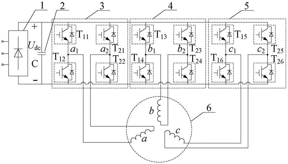
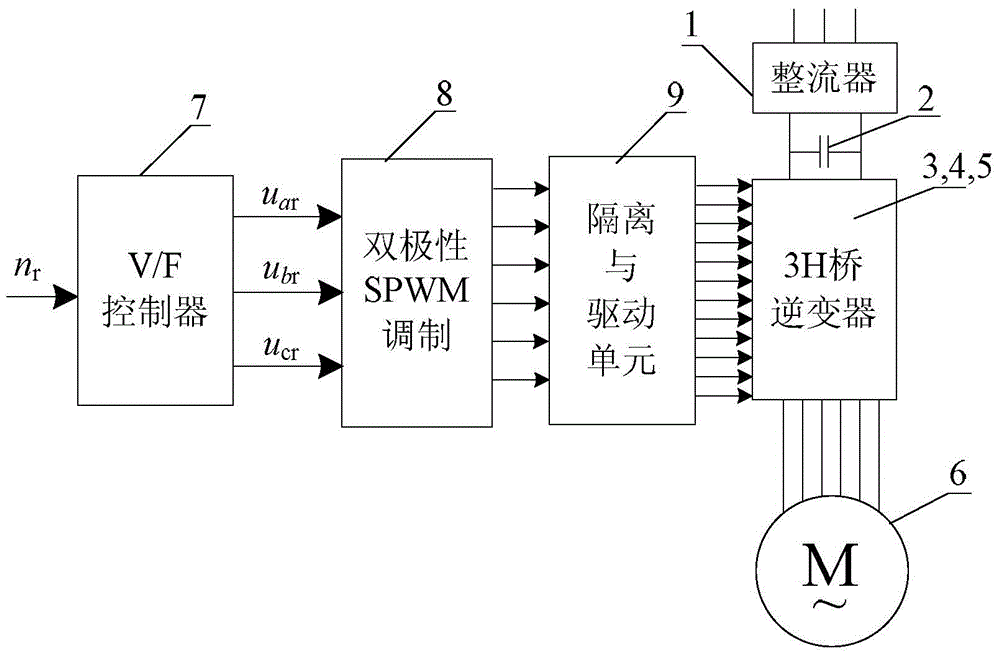
[0014] Specific implementation mode one: the following combination figure 1 and figure 2 Describe this embodiment, the drive controller of the open winding induction motor 3H bridge drive system described in this embodiment, it includes a rectifier 1, a DC filter capacitor 2, a 3H bridge inverter, a V / F controller 7, a bipolar SPWM modulation 8 and isolation and drive unit 9; 3 H-bridge inverter is composed of A-phase H-bridge inverter 3, B-phase H-bridge inverter 4 and C-phase H-bridge inverter 5;

[0015] A DC filter capacitor 2, an A-phase H-bridge inverter 3, a B-phase H-bridge inverter 4, and a C-phase H-bridge inverter 5 are sequentially connected in parallel on the DC bus output by the rectifier 1;

[0016] The A-phase winding of the open-winding induction motor 6 is connected in parallel between the two AC output terminals of the A-phase H-bridge inverter 3;

[0017] The B-phase winding of the open-winding induction motor 6 is connected in parallel between the two A...

specific Embodiment approach 2

[0026] Specific implementation mode two: the following combination Figure 3 to Figure 5 Describe this embodiment mode, this embodiment mode is further explained to embodiment mode 1, the control of bipolar SPWM modulation 8 pairs of 3H bridge inverters is realized by DSP digitally, and the control process is:

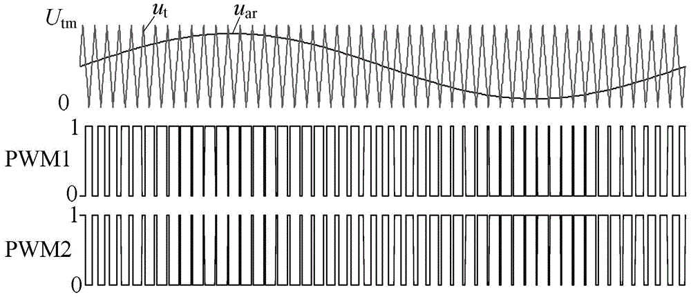
[0027] V / F controller 7 according to the speed command n r Calculate the amplitude and frequency of the voltage required by the motor, and then generate three-phase symmetrical sinusoidal modulation waves u ar , u br , u cr ; The timer T1 of DSP is used to produce the triangular carrier of fixed amplitude and frequency; The three-phase sinusoidal modulation wave is compared with the triangular carrier to generate 6 PWM switching signals.

[0028] image 3 It is the a-phase bipolar SPWM modulation waveform of the present invention. By sinusoidally modulating the wave u in the DSP ar Generate triangular wave u with timer T1 t The comparison of two channels of comp...

specific Embodiment approach 3

[0031] Specific implementation mode three: this implementation mode will further explain the first embodiment mode, the V / F controller 7 according to the speed command n r Calculate the amplitude and frequency of the voltage required by the motor, and then generate three-phase symmetrical sinusoidal modulation waves u ar , u br , u cr The process is:

[0032] First, according to the speed command n r and motor rated slip s N Calculate the synchronous speed n s :

[0033] n s = n r 1 - s N ;

[0034] Second, the synchronous speed n s Converted to motor stator current frequency f 1 :

[0035] In the formula, p is the number of pole pairs of the motor;

[0036] Then, according to the constraints of the induction motor voltage and frequency, calculate at frequency...


PUM


Abstract

The invention provides a three-phase H-bridge driving system for an open type winding induction motor and belongs to the field of motor control. The three-phase H-bridge driving system aims to solve the problem that a double-inverter modulation algorithm adopted for an existing open type winding induction motor is complex. According to the scheme, a DC filter capacitor, an A-phase H-bridge inverter, a B-phase H-bridge inverter and a C-phase H-bridge inverter are sequentially connected to a DC bus output from a rectifier in parallel; an A-phase winding of the open type winding induction motor is connected between two AC output ends of the A-phase H-bridge inverter in parallel, a B-phase winding of the open type winding induction motor is connected between two AC output ends of the B-phase H-bridge inverter in parallel, and a C-phase winding of the open type winding induction motor is connected between two AC output ends of the C-phase H-bridge inverter in parallel; a V / F controller receives a rotational speed instruction nr and outputs three-phase symmetric sinusoidal modulated waves uar, ubr and ucr to a bipolar SPWM modulator; the bipolar SPWM modulator compares the three-phase symmetric sinusoidal modulated waves uar, ubr and ucr with triangular carrier signals to generate six-channel switching signals, and then outputs 12-channel driving signals to the A-phase H-bridge inverter, the B-phase H-bridge inverter and the C-phase H-bridge inverter through an isolation and driving unit.

Description

technical field [0001] The invention relates to a driving system of a motor, which belongs to the field of motor control. Background technique [0002] Induction motor frequency conversion speed regulation system is widely used in industrial traction, electric locomotive traction and other fields. The windings of traditional induction motors are star-connected, powered by a two-level inverter, and the DC voltage utilization rate is low. In order to increase the output voltage of the inverter, multi-level inverter topologies such as diode clamp type, flying capacitor type, and cascaded type have appeared. These multi-level inverters have many devices, complex structure and control, and capacitors. The voltage needs to be balanced and controlled, which limits its application. In order to solve the above problems, the neutral point of the motor winding can be separated to form a three-phase independent open-winding induction motor, and the three-phase winding is powered by th...

Claims


Application Information

Patent Timeline
Patent Type & Authority Patents(China)
IPC IPC(8): H02P27/08H02P25/16
CPCH02P25/16H02P27/047H02P27/08
Inventor 安群涛孙立志孙力邹存芝赵克
Owner 严格集团股份有限公司
Why Eureka
Try Eureka