Suction structure, robot hand and robot
An adsorption structure and suction cup technology, applied in the directions of robots, manipulators, conveyor objects, etc., can solve the problems of increasing size, inability to adsorb the substrate, and fix the substrate, and achieve the effect of reliable adsorption
- Summary
- Abstract
- Description
- Claims
- Application Information
AI Technical Summary
Problems solved by technology
Method used
Image

Examples
no. 1 approach
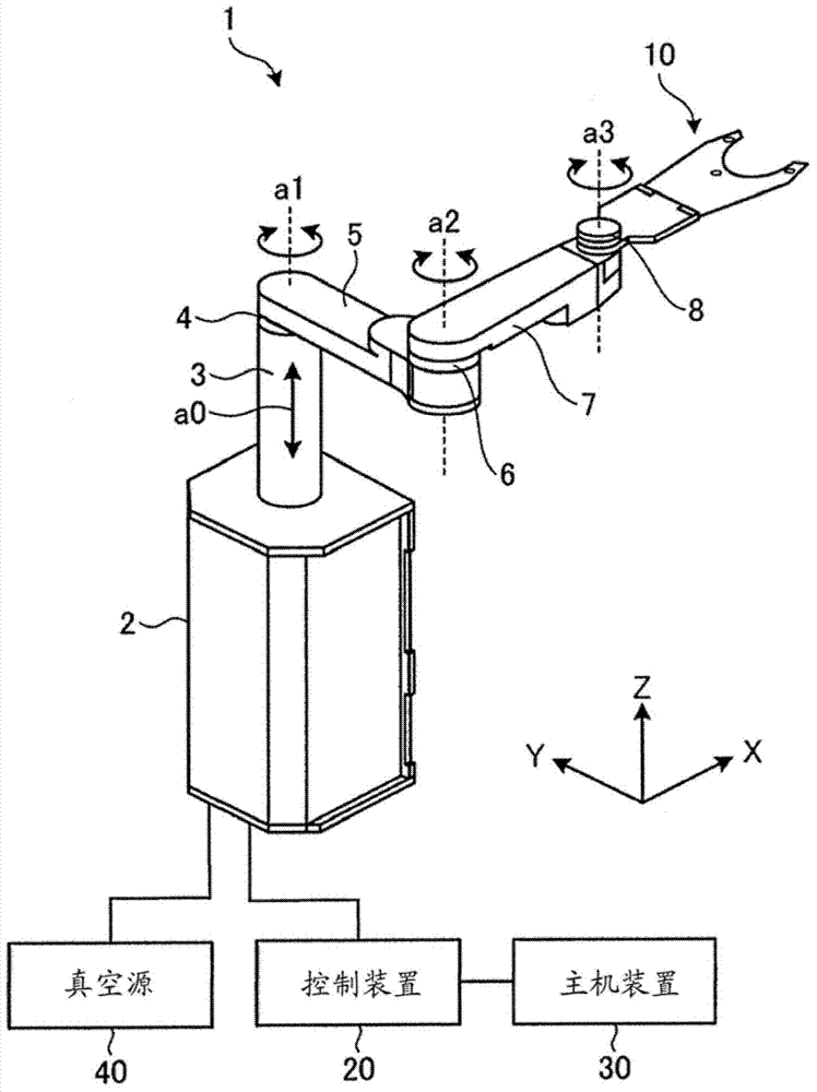
[0037] First, refer to figure 1 The structure of the robot 1 according to the first embodiment will be described. figure 1 is a schematic perspective view of the robot 1 according to the first embodiment.
[0038] For easy understanding, in figure 1 shows a three-dimensional orthogonal coordinate system including a Z-axis with vertical upward as a positive direction and vertical downward as a negative direction. Therefore, the direction extending along the XY plane means "horizontal direction". This orthogonal coordinate system may also be shown in other drawings used in the following description.
[0039] In the following description, for ease of explanation, it is assumed that the swing position and direction of the robot 1 are at figure 1 The state shown is to explain the positional relationship among the parts of the robot 1 .
[0040] In the following description, there are cases where, for a large number of components, some components are given reference numerals an...
no. 2 approach
[0097] Figure 5A is a schematic plan view of a suction pad 13A according to the second embodiment. Figure 5B is along Figure 5A The schematic cross-sectional view cut by the line VB-VB'. In the second embodiment, components different from those of the first embodiment will be mainly described.
[0098] Such as Figure 5A As shown, unlike the suction cup 13 of the first embodiment, the suction cup 13A of the second embodiment further includes a flange (rim) portion 13d extending and protruding in a linear shape from the outer peripheral edge of the contact portion 13a.
[0099] Such as Figure 5B As shown, the flange portion 13d is provided at the same height as the main surface portion 13b so as to continuously extend from the main surface portion 13b. The support body 15 is fixedly mounted on the lower surface (back surface) of the flange portion 13d so as to elastically support the suction pad 13A only at a portion around the outer peripheral edge of the flange porti...
no. 3 approach
[0122] Figure 8A is a schematic plan view of the suction pad 13B according to the third embodiment. Figure 8B and Figure 8C is along Figure 8A The schematic cross-sectional view cut by the line VIIIB-VIIIB'.
[0123] In the third embodiment, components different from those of the first and second embodiments will be mainly explained. The shape of the suction pad 13B is substantially the same as that of the suction pad 13A of the second embodiment.
[0124] Such as Figure 8A As shown, the suction pad 13B according to the third embodiment includes a support body 15A elastically supporting its outer peripheral surface at the side.
[0125] Specifically, as Figure 8B As shown, on the inner peripheral surface of the annular wall portion 12b of the plate 12, the support body 15A elastically supports the outer peripheral surface of the suction cup 13B at its side. A supporting body 15A, which is a substantially annular elastic body, is fixed to the plate 12 so as to surr...
PUM
 Abstract
Description
Claims
Application Information
 - R&D
- Intellectual Property
- Life Sciences
- Materials
- Tech Scout
- Unparalleled Data Quality
- Higher Quality Content
- 60% Fewer Hallucinations
Browse by: Latest US Patents, China's latest patents, Technical Efficacy Thesaurus, Application Domain, Technology Topic, Popular Technical Reports.
© 2025 PatSnap. All rights reserved.Legal|Privacy policy|Modern Slavery Act Transparency Statement|Sitemap|About US| Contact US: help@patsnap.com