Suction structure, robot hand and robot
An adsorption structure and suction cup technology, which is applied in the direction of manipulators, conveyor objects, semiconductor/solid-state device manufacturing, etc., can solve the problems of increased size, reduced substrate thickness, and inability to absorb substrates, and achieve the effect of reliable adsorption.
- Summary
- Abstract
- Description
- Claims
- Application Information
AI Technical Summary
Problems solved by technology
Method used
Image

Examples
no. 1 approach
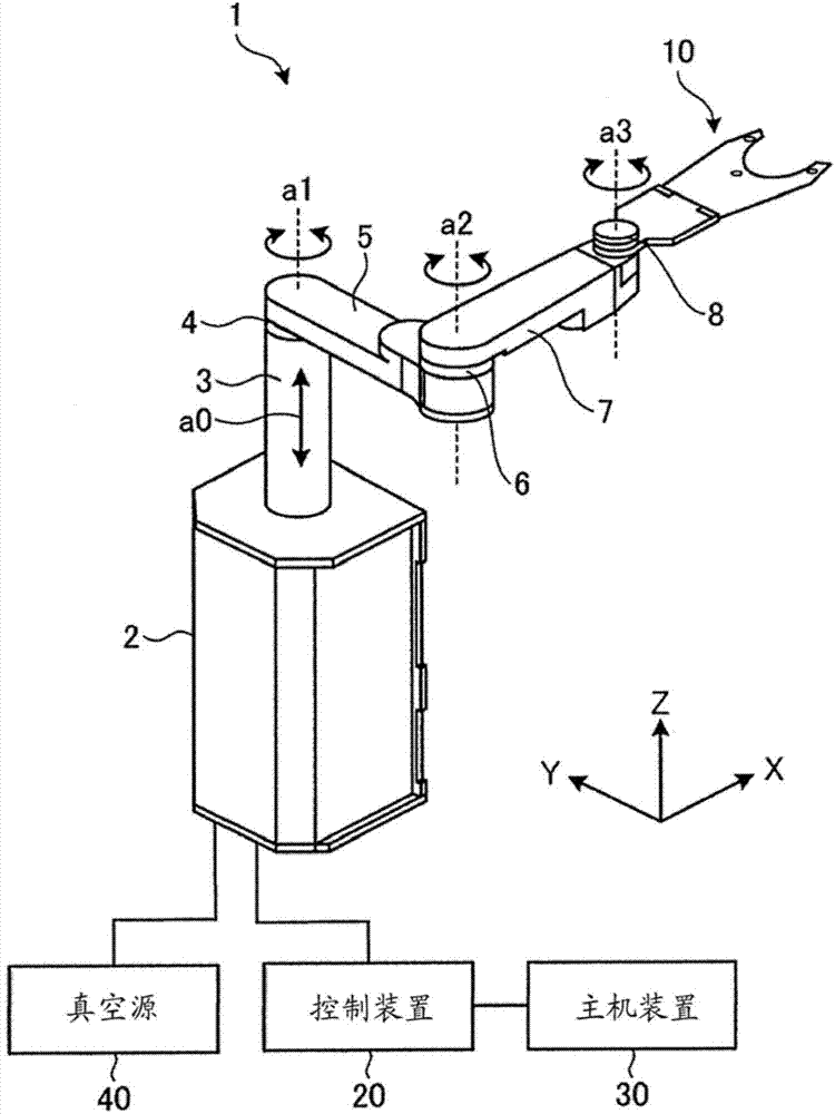
[0037] First, refer to figure 1 The structure of the robot 1 according to the first embodiment will be described. figure 1 It is a schematic perspective view of the robot 1 according to the first embodiment.
[0038] For easy understanding, in figure 1 A three-dimensional orthogonal coordinate system including a Z-axis with the vertical upward as the positive direction and the vertical downward as the negative direction is illustrated in . Therefore, the direction extending along the XY plane represents the "horizontal direction". This orthogonal coordinate system may also be shown in other drawings used in the following description.
[0039] In the following description, for convenience of description, it is assumed that the swing position and direction of the robot 1 are in figure 1 In the state shown, the positional relationship between the parts of the robot 1 will be described.
[0040] In the following description, there are cases where, among many components, refer...
no. 2 approach
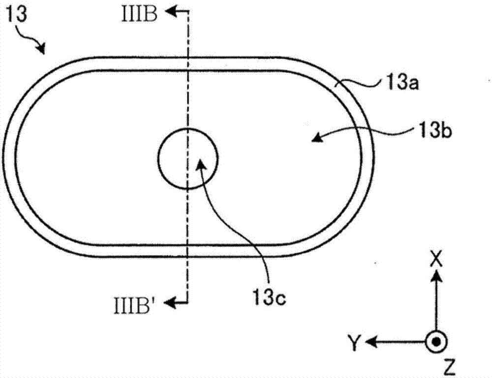
[0097] Figure 5A It is a schematic plan view of the suction cup 13A according to the second embodiment. Figure 5B is along Figure 5A A schematic cross-sectional view of the line VB-VB'. In the second embodiment, components different from those of the first embodiment will be mainly described.
[0098] like Figure 5A As shown, unlike the suction cup 13 of the first embodiment, the suction cup 13A of the second embodiment further includes a flange (rim) portion 13d extending and protruding from the outer peripheral edge of the contact portion 13a in a rim-like shape.
[0099] like Figure 5B As shown, the flange portion 13d is provided at the same height as the main surface portion 13b so as to extend continuously from the main surface portion 13b. The support body 15 is fixedly attached to the lower surface (back surface) of the flange portion 13d so as to elastically support the suction cup 13A only in a portion surrounding the outer peripheral edge of the flange port...
no. 3 approach
[0122] Figure 8A It is a schematic plan view of the suction cup 13B according to the third embodiment. Figure 8B and Figure 8C is along Figure 8A A schematic cross-sectional view taken along the line VIIIB-VIIIB'.
[0123] In the third embodiment, components different from those of the first and second embodiments will be mainly described. The shape of the suction cup 13B is substantially the same as that of the suction cup 13A of the second embodiment.
[0124] like Figure 8A As shown, the suction cup 13B according to the third embodiment includes a support body 15A that elastically supports its outer peripheral surface at the side.
[0125] Specifically, as Figure 8B As shown, on the inner circumferential surface of the annular wall portion 12b of the plate 12, the support body 15A elastically supports the outer circumferential surface of the suction pad 13B at the side thereof. The support body 15A, which is a substantially annular elastic body, is fixed to the...
PUM
 Abstract
Description
Claims
Application Information
 - R&D Engineer
- R&D Manager
- IP Professional
- Industry Leading Data Capabilities
- Powerful AI technology
- Patent DNA Extraction
Browse by: Latest US Patents, China's latest patents, Technical Efficacy Thesaurus, Application Domain, Technology Topic.
© 2024 PatSnap. All rights reserved.Legal|Privacy policy|Modern Slavery Act Transparency Statement|Sitemap