Low-voltage management system and method of distributed battery management system

A battery management system and a management system technology, applied in the field of battery management, can solve the problems of inability to realize low-voltage power management, difficulty in determining the current overload parameters of the main node, and current overload of the main node.

Active Publication Date: 2015-01-14
HUIZHOU EPOWER ELECTRONICS
View PDF6 Cites 8 Cited by
  • Summary
  • Abstract
  • Description
  • Claims
  • Application Information

AI Technical Summary

Problems solved by technology

[0002] Generally speaking, the low-voltage connection, power-on and power-off management of the existing distributed battery management system is to use the working power of each sub-node of the system to be provided by the main node. After the main node is powered off at low voltage, the sub-nodes are powered off at the same time. , this connection method has the following disadvantages: the working current consumed by all sub-nodes must pass through the main node, which may cause the current overload of the main node, and due to different application designs, the number of sub-nodes in the system is inconsistent. It is difficult to determine the current overload parameters of the main node; the power supply of each sub-node is completely controlled by the main node, and it is impossible to realize its own low-voltage power management. For example, sub-nodes need to save necessary data before powering off at low voltage, and turn off some devices, etc.

Method used


Image

  • Low-voltage management system and method of distributed battery management system
  • Low-voltage management system and method of distributed battery management system
  • Low-voltage management system and method of distributed battery management system

Examples


Embodiment Construction

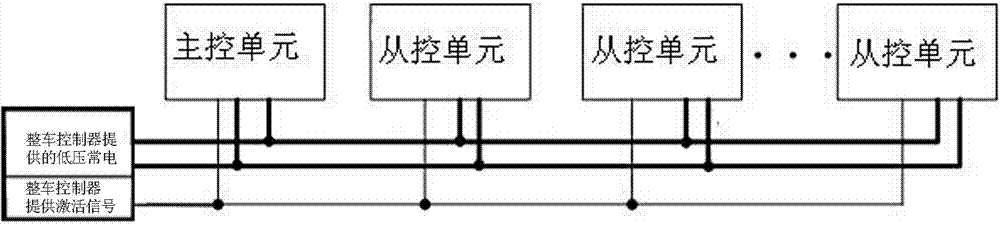
[0021] Such as figure 1 As shown, a low-voltage management system of a distributed battery management system includes a master control unit, multiple slave control units and a vehicle controller, and also includes a set of power lines, and the low-voltage constant power terminal of the vehicle controller Connected with the power line to provide low-voltage constant power for the master control unit and the slave control unit, the power line is provided with a master node and multiple sub-nodes, and the master node is connected to the master control unit to directly master The control unit provides power, and any one of the sub-nodes is individually connected to a slave control unit to directly provide power for the slave control unit at the same time. The main control unit is also connected to the vehicle controller through one channel of the CAN bus to receive information about whether the vehicle controller needs to be powered off at low voltage, and at the same time connect...


PUM


Abstract

The invention discloses a low-voltage management system of a distributed battery management system. The low-voltage management system comprises a master control unit, a plurality of slave control units controlled by the master control unit and a group of power supply circuit, wherein the power supply circuit connects the master control unit and the slave control units in parallel to a power supply output end of a finished vehicle controller; a main node and a plurality of branch nodes are designed on the power supply circuit; the main node is connected with the master control unit to directly power the master control unit; any branch node is independently connected to one slave control unit to directly power the slave control unit simultaneously. The synchronism between low-voltage powering on and powering off of the distributed battery management system and the finished vehicle controller is realized, and meanwhile, the synchronism between low-voltage power supply powering on and powering off of each node in the distributed battery management system is realized.

Description

technical field [0001] The invention relates to the field of battery management, in particular to a low-voltage management system and method of a distributed battery management system. Background technique [0002] Generally speaking, the low-voltage connection, power-on and power-off management of the existing distributed battery management system is to use the working power of each sub-node of the system to be provided by the main node. After the main node is powered off at low voltage, the sub-nodes are powered off at the same time. , this connection method has the following disadvantages: the working current consumed by all sub-nodes must pass through the main node, which may cause the current overload of the main node, and due to different application designs, the number of sub-nodes in the system is inconsistent. It is difficult to determine the current overload parameters of the main node; the power supply of each sub-node is completely controlled by the main node...

Claims


Application Information

Patent Timeline
Patent Type & Authority Applications(China)
IPC IPC(8): B60L3/00G05B19/04
Inventor 刘飞文锋阮旭松王占国阮廷军
Owner HUIZHOU EPOWER ELECTRONICS
Why Eureka
Try Eureka