
Four-hydraulic-motor-driven self-synchronizing vibrating hammer and structural parameter determining method thereof

A technology of self-synchronized vibration and hydraulic motors, which is applied in infrastructure engineering, electrical digital data processing, special data processing applications, etc., can solve problems such as short life, low reliability of vibratory hammer, and no consideration

Inactive Publication Date: 2015-01-14
NORTHEASTERN UNIV
View PDF6 Cites 10 Cited by
  • Summary
  • Abstract
  • Description
  • Claims
  • Application Information

AI Technical Summary

Problems solved by technology

According to the transmission type, it can be divided into rigid synchronous type and self-synchronized type. In the synchronous mode of gear rigid transmission, the transmission gear is frequently damaged after being impacted, resulting in low reliability and short life of the vibratory hammer.
At present, the design of vibratory hammers mostly adopts the method of direct drive by motor and rigid synchronous transmission of gears. This design structure is complex and causes many practical problems.
Moreover, the impact of the dynamic coupling characteristics of the vibratory hammer itself on the synchronization is not considered when designing the vibratory hammer. To avoid the problems caused by the rigid synchronous transmission gear and improve the stability and service life of the vibratory hammer, the structure of the vibratory hammer must be innovatively designed.

Method used

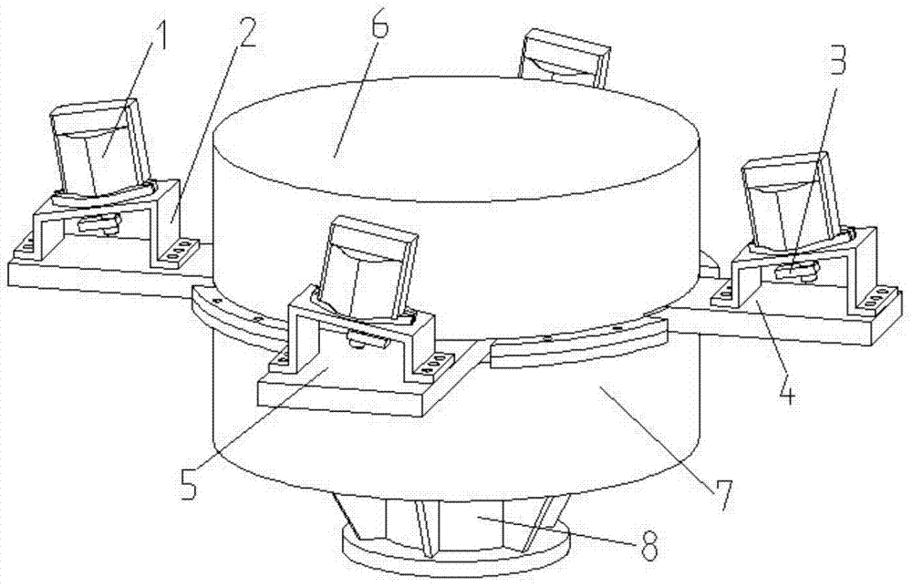

Image

  • Four-hydraulic-motor-driven self-synchronizing vibrating hammer and structural parameter determining method thereof
  • Four-hydraulic-motor-driven self-synchronizing vibrating hammer and structural parameter determining method thereof
  • Four-hydraulic-motor-driven self-synchronizing vibrating hammer and structural parameter determining method thereof

Examples


Embodiment Construction

[0051] The specific implementation manners of the present invention will be described in detail below in conjunction with the accompanying drawings.

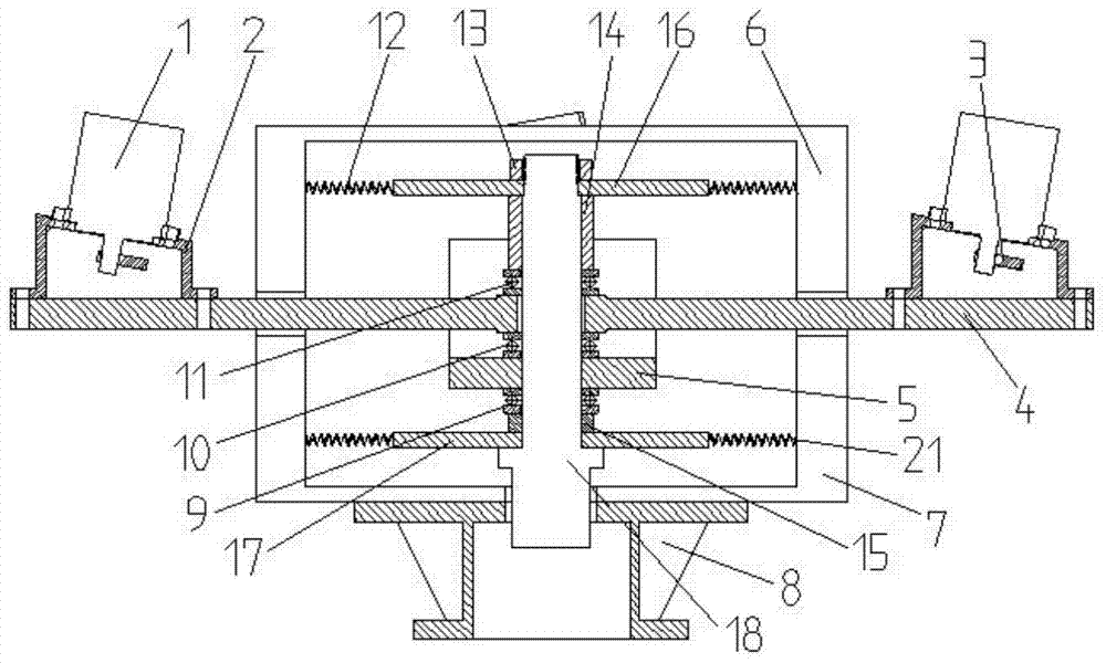
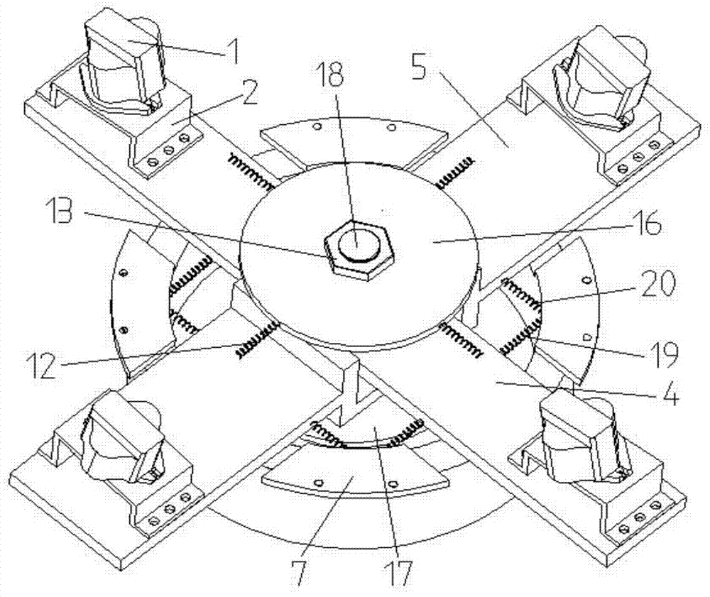
[0052] Such as figure 1 with figure 2 As shown, a self-synchronizing vibratory hammer driven by four hydraulic motors includes four hydraulic motors 1, an upper rotating beam 4, a lower rotating beam 5, a transmission shaft 18, a pile clamp 8, an upper plate 16, a lower plate 17, and an upper chassis 6 and lower chassis 7;

[0053] There are through holes in the middle of the upper rotating beam 4, the lower rotating beam 5, the upper plate 16 and the lower plate 17;

[0054] The transmission shaft 18 is vertically arranged, the upper rotating beam 4, the lower rotating beam 5, the upper plate 16, and the lower plate 17 are all sleeved outside the transmission shaft 18, the upper plate 16 is fixedly connected with the transmission shaft 18, the upper rotating beam 4, and the lower rotating beam 5 Both are located between the...


PUM


Abstract

The invention provides a four-hydraulic-motor-driven self-synchronizing vibrating hammer and a structural parameter determining method thereof. The four-hydraulic-motor-driven self-synchronizing vibrating hammer comprises four hydraulic motors, an upper rotating beam, a lower rotating beam, a transmission shaft, a pile clamp, an upper plate, a lower plate, an upper cabinet and a lower cabinet. The structural parameter determining method includes building a same-direction rotation dynamic model of the four-hydraulic-motor-driven self-synchronizing vibrating hammer; acquiring a dimensionless coupling equation of four eccentric rotors; acquiring conditions for the eccentric rotors to realize synchronization; acquiring stability conditions for the eccentric rotors to realize synchronous running so as to determine structural parameters of the four-hydraulic-motor-driven self-synchronizing vibrating hammer. Effect, of system vibrating coupling characteristics, on improving synchronicity is taken into consideration, a mode of hydraulic motor driving and self-synchronizing transmission is adopted for creative designing of structure of the vibrating hammer, and the objective of four-hydraulic-motor driving and self-synchronizing is achieved by controlling the structural parameters of the vibrating hammer.

Description

technical field [0001] The invention belongs to the technical field of vibration machinery, and in particular relates to a self-synchronizing vibration hammer driven by four hydraulic motors and a method for determining its structural parameters. Background technique [0002] Vibratory hammer is the key mechanical equipment for foundation construction in the construction industry, and is widely used in pile sinking and pulling operations for large-scale foundation projects such as urban construction, bridges, and ports. Vibratory hammer can be divided into electric type and hydraulic type according to the classification of prime mover. Compared with electric vibratory hammer, hydraulic vibratory hammer has the characteristics of convenient frequency modulation, good pile sinking effect, low noise, impact resistance, and wide range of geological applications. According to the transmission type, it can be divided into rigid synchronous type and self-synchronized type. In the s...

Claims


Application Information

Patent Timeline
IPC IPC(8): E02D7/18G06F17/50
CPCE02D7/18G06F30/17
Inventor 赵春雨赵乾斌刘军江王海洋张义民闻邦椿
Owner NORTHEASTERN UNIV
Learn More