an impeller structure

A technology of impeller and impeller cover, which is applied to components of pumping devices for elastic fluids, non-variable pumps, machines/engines, etc. It can solve the problems of high energy consumption, low structural performance of impellers, and high cost of use. Achieve the effects of low energy consumption, compact structure and low cost of use

Active Publication Date: 2018-01-30
KINGCLEAN ELECTRIC
View PDF12 Cites 1 Cited by
  • Summary
  • Abstract
  • Description
  • Claims
  • Application Information

AI Technical Summary

Problems solved by technology

[0006] In order to reduce the overall volume of the vacuum cleaner, it is generally driven by a brushless motor. In order to meet the use requirements of the brushless motor, the impeller structure generally needs to be made smaller. The traditional aluminum closed impeller is no longer suitable for the brushless motor, and the traditional The structural performance of the impeller is low, the energy consumption is large, and the use cost is high

Method used


Image

  • an impeller structure
  • an impeller structure
  • an impeller structure

Examples


Embodiment Construction

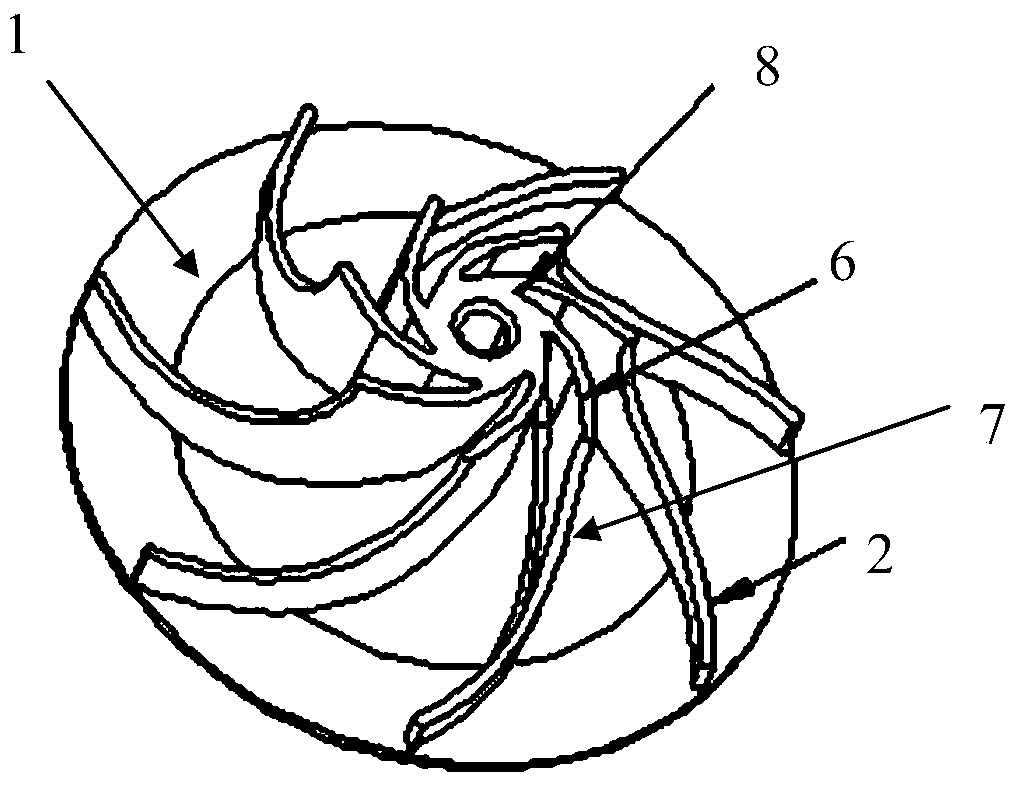
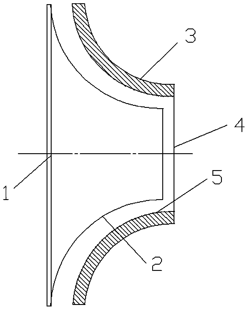
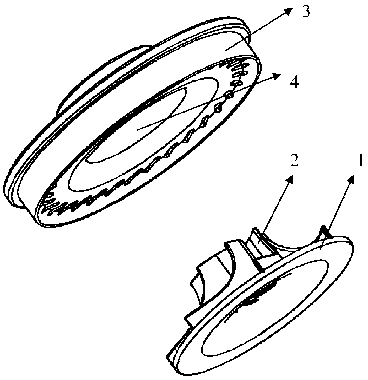
[0029] The impeller of the traditional vacuum cleaner motor is an aluminum impeller, which is a closed impeller structure, usually including an upper cover, a lower cover, and blades arranged between the upper and lower covers. The working efficiency of the closed impeller is relatively high. However, it is difficult to manufacture, and the upper and lower cover plates and blades of the aluminum impeller are assembled, the structure is complex, the volume is generally large, the quality is heavy, the production cost is high, and the noise is relatively large during operation. Compared with the closed impeller, the semi-open impeller and the open impeller are relatively smaller in volume, but their work efficiency is low, and they cannot meet the needs of high-speed use.

[0030] Aiming at the deficiencies in the prior art, the present invention provides an impeller structure. By adopting the impeller structure in which the lower cover plate and blades are integrally formed to m...


PUM


Abstract

An impeller structure comprising a lower cover (1) and multiple arced blades (2) designed on the lower cover (1). The blades (2) are connected to a shaft (8) and involutely distributed along the lower cover (1). The impeller structure is applicable in a high vacuum, high rotational speed brushless direct-current vacuum cleaner motor. The impeller structure is a semi-opened impeller structure and relatively small in size, reduces the amount of materials used, and is inexpensive to manufacture. An impeller cover (3) is arranged above the blades (2). The blades (2) and the impeller cover (3) are in an interference fit. The impeller cover (3) also serves as an upper cover in the structure and is assembled together with the lower cover (1) and the blades (2) into a closed impeller structure, thus not only reducing motor size but also ensuring work efficiency of the impeller.

Description

technical field [0001] The invention belongs to the technical field of production and manufacture of vacuum cleaner motors, and in particular relates to an impeller structure. Background technique [0002] The vacuum cleaner is a cleaning appliance that uses a motor to drive the blades to rotate at high speed, and generates air negative pressure in the sealed housing, thereby sucking dust into the dust bag. Vacuum cleaners can generally be divided into vertical, horizontal and portable according to their structural composition. [0003] The vacuum cleaner motor is the core component of the vacuum cleaner. It generally consists of two parts, the motor part and the fan part. Because the vacuum cleaner motor has high requirements on the speed, usually at 20,000-30,000 revolutions per minute, the conventional vacuum cleaner motor generally uses a series-excited vacuum cleaner motor. and small DC vacuum cleaner motors. Both the series-excited vacuum cleaner motor and the small D...

Claims


Application Information

Patent Timeline
Patent Type & Authority Patents(China)
IPC IPC(8): F04D29/26
CPCF04D29/28F04D29/30
Inventor 倪祖根薛峰
Owner KINGCLEAN ELECTRIC
Why Eureka
Try Eureka