Control method of synchronizer in vehicle and vehicle

A synchronizer, vehicle technology, applied in control devices, vehicle components, engine control and other directions, can solve the problems of complex power transmission system structure, complex control strategy, low transmission efficiency, etc., to achieve the best fuel economy, excellent stability and peace of mind. Compliant, smooth running effect

Active Publication Date: 2015-11-25
BYD CO LTD
View PDF5 Cites 0 Cited by
  • Summary
  • Abstract
  • Description
  • Claims
  • Application Information

AI Technical Summary

Problems solved by technology

[0003] However, in the related technologies known to the inventor, the power transmission system in a hybrid vehicle is generally complex in structure, bulky, and low in transmission efficiency. The strategy is complicated and needs to be improved

Method used


Image

  • Control method of synchronizer in vehicle and vehicle
  • Control method of synchronizer in vehicle and vehicle
  • Control method of synchronizer in vehicle and vehicle

Examples


Embodiment 1

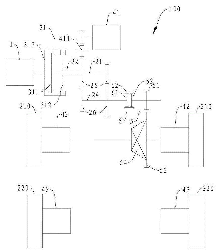
[0152] Such as figure 2 As shown, the engine unit 1 is connected to the input end 313 of the double clutch 31, the first output end 311 of the double clutch 31 is connected to the first input shaft 21, and the second output end 312 of the double clutch 31 is connected to the second input shaft 22, The second input shaft 22 is coaxially sleeved on the first input shaft 21 .

[0153] A driving gear 25 is fixedly arranged on the first input shaft 21 and the second input shaft 22 respectively, and the first motor generator 41 is indirectly driven with the driving gear 25 on the second input shaft 22 through an intermediate gear 411 . Two driven gears 26 are fixedly arranged on the output shaft 24 , and the two driven gears 26 respectively mesh with the driving gears 25 on the first input shaft 21 and the second input shaft 22 to form two transmission gears.

[0154] The synchronizer 6 is arranged on the output shaft 24, and the driving gear of the main reducer (that is, the outp...

Embodiment 2

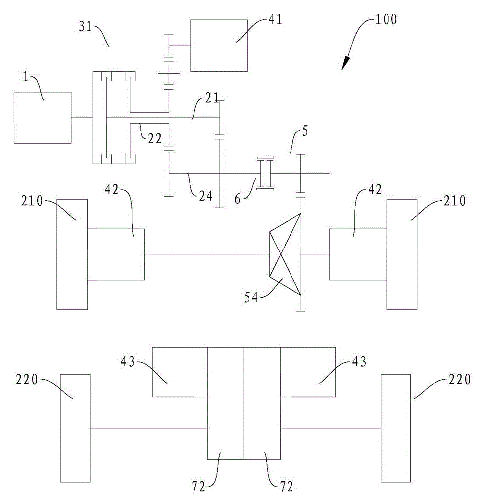
[0182] Such as image 3 As shown, the power transmission system 100 in this embodiment and figure 2 The difference of the power transmission system 100 in the above may only lie in the arrangement form of the second motor generator 43 . In this embodiment, each second motor-generator 43 drives the corresponding rear wheel 220 through a second speed change mechanism 72, and the remaining parts can be connected with figure 2 The power transmission system 100 in the embodiment is basically the same, and will not be repeated here. As for the specific working conditions, it is related to figure 2 The power transmission system 100 in the embodiment is basically the same, and the only difference is that the power transmission between the second motor generator 43 and the corresponding rear wheel 220 needs to go through the second transmission mechanism 72 , which will not be described in detail here.

Embodiment 3

[0184] Such as Figure 4 As shown, the power transmission system 100 in this embodiment and figure 2 The difference of the power transmission system 100 in the above may only lie in the arrangement form of the second motor generator 43 . In this embodiment, the second motor-generator 43 is one and drives the corresponding rear wheel 220 through a first speed change mechanism 71, and the remaining parts can be connected with figure 2 The power transmission system 100 in the embodiment is basically the same, and will not be repeated here. As for the specific working conditions, it is related to figure 2 The power transmission system 100 in the embodiment is basically the same, and the only difference is that the two rear wheels 220 are driven by a second motor-generator 43 and a first speed change mechanism 71, so without adding new components, only The differential function of the two rear wheels 220 cannot be realized by a motor and a transmission mechanism, but it can b...


PUM


Abstract

A method for controlling a synchronizer (6) of a vehicle is provided. The vehicle includes an engine unit (1), a transmission unit (2a), an output unit (5), a synchronizer (6), first and second motor generators (41, 42) and a power battery (not shown). The transmission unit (2a) is configured to selectively couple with the engine unit (1). The output unit (5) is configured to transmit a power transmitted by the transmission unit (2a) to at least one of front and rear wheels (210, 220) of the vehicle. The synchronizer (6) is configured to enable or interrupt a power transmission between the transmission unit (2a) and the output unit (5) and to selectively synchronize the output unit (5) and the transmission unit (2a). The first motor generator (41) is coupled with the transmission unit (2a) and configured to adjust a rotating speed of an output shaft (24) coupled with the synchronizer (6) according to a speed of the vehicle. The second motor generator (42) is configured to drive at least one of the front and rear wheels (210, 220). The power battery is coupled with the first and second motor generators (41, 42), respectively. The method includes acquiring an operation mode and operation parameters of the vehicle; and controlling the synchronizer (6) to engage or to disengage based on the operation parameters.

Description

technical field [0001] The invention relates to the technical field of automobile construction, in particular to a method for controlling a synchronizer in a vehicle and the vehicle. Background technique [0002] With the continuous consumption of energy, the development and utilization of new energy vehicles has gradually become a trend. As one of the new energy vehicles, a hybrid vehicle is driven by an internal combustion engine and / or an electric motor, and has multiple modes, which can improve transmission efficiency and fuel economy. [0003] However, in the related technologies known to the inventor, the power transmission system in a hybrid electric vehicle is generally complex in structure, bulky, and low in transmission efficiency. The strategy is complex and needs to be improved. Contents of the invention [0004] The present invention aims to solve one of the above-mentioned technical problems in the prior art at least to a certain extent. [0005] Therefore...

Claims


Application Information

Patent Timeline
Patent Type & Authority Patents(China)
IPC IPC(8): F16H61/04
CPCB60W20/20B60K6/387B60K6/442B60K6/52B60K7/0007B60K17/356B60W10/02B60W10/08B60W10/113B60W20/40F16H37/065Y10S903/93Y10T74/19014Y10T477/328F16H61/02F16H2061/0422B60W10/06B60W30/18127B60W30/18172B60W2510/081B60W2510/244B60W2520/10B60W2540/10B60W2710/081B60W20/14Y02T10/62
Inventor 杨冬生廉玉波张金涛罗红斌
Owner BYD CO LTD
Why Eureka
Try Eureka