Single chip difference free layer push-pull type magnetic field sensor electric bridge and preparation method thereof
一种磁场传感器、推挽式的技术,应用在磁性传感器领域,能够解决影响两轴或三轴传感器测量精度、增加工艺复杂性、影响传感器测量精度等问题
- Summary
- Abstract
- Description
- Claims
- Application Information
AI Technical Summary
Problems solved by technology
Method used
Image
Examples
Embodiment 1
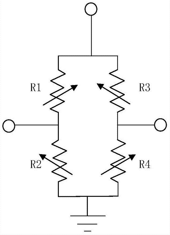
[0090] figure 1 It is a full-bridge structure diagram of a push-pull magnetoresistive sensor, including four bridge arms R1, R2, R3 and R4, where R1 and R4 are push arms, and R2 and R3 are pull arms. For magnetoresistive sensors, push arms and pull arms Under the action of the external magnetic field, the arms have the characteristics of opposite magnetic field changes. For the GMR spin valve and TMR type magnetoresistive sensing units, it means that the angle between the magnetization directions of the free layer and the pinned layer increases (decreases) and decreases respectively. Small (increased), and the magnitude of the change is the same.
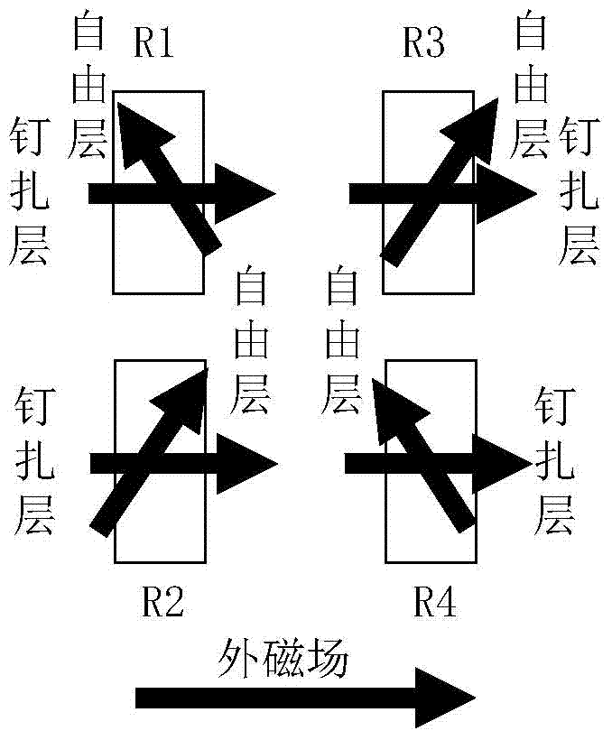
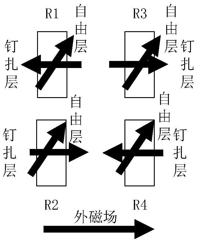
[0091] Figure 2a , 2b are the two possible cases of the magnetization state in a push-pull magnetoresistive sensor of GMR spin valve or TMR type, Figure 2b In the case of flipping the pinned layer, the magnetization direction of the pinned layer in the push arm magnetoresistive sensing unit and the pull arm magnetoresistive sen...
Embodiment 2
[0094] image 3 The invention proposes to use a soft magnetic flux concentrator to transform the same Y-direction measurement external magnetic field H into a magnetic field distribution with opposite two X-component magnetic fields and the position diagram of the corresponding push magneto-resistance sensing unit and pull magneto-resistance sensing unit. Among them, the soft magnetic flux concentrator 1 has sides parallel to the X and Y axes, and has four corners, which are marked as A, B, C and D in a clockwise direction from the upper left, and the Y outward magnetic field H passes through the flux concentrator After 1, the magnetic field is distorted near the flux concentrator 1, and in addition to the Y magnetic field component, an X magnetic field component also appears, where the magnetic field near angular position D and angular position B has a positive X magnetic field component at angular position A and the magnetic field near the angular position C has a negative X...
Embodiment 3
[0098] Figure 4 with Figure 5For the structural diagram of the single-chip differential free layer push-pull magnetoresistive sensor proposed by the present invention and its measurement principle diagram to the external magnetic field in the X and Y directions, including the substrate positioned on the X-Y plane, the first and 12 are composed of 11 That is, the second two soft magnetic flux concentrator arrays are staggered to form a soft magnetic flux concentrator array, and a magnetoresistive sensor array 35 composed of a push magnetoresistance sensing unit and a pull magnetoresistance sensing unit. The row direction of the soft magnetic flux concentrator array is parallel to the X axis, and the column direction is parallel to the Y axis. The gap in the Y direction is ygap, and the gaps in the X direction are xgap and rgap, that is, along the positive X direction, the first soft magnetic flux concentrator The X-direction gap between the first column and the first column ...
PUM
 Abstract
Description
Claims
Application Information
 - R&D
- Intellectual Property
- Life Sciences
- Materials
- Tech Scout
- Unparalleled Data Quality
- Higher Quality Content
- 60% Fewer Hallucinations
Browse by: Latest US Patents, China's latest patents, Technical Efficacy Thesaurus, Application Domain, Technology Topic, Popular Technical Reports.
© 2025 PatSnap. All rights reserved.Legal|Privacy policy|Modern Slavery Act Transparency Statement|Sitemap|About US| Contact US: help@patsnap.com


