
Vertical microwave photo-oxidative catalytic waste gas purifier

An exhaust gas purifier and microwave light technology, applied in chemical instruments and methods, dispersed particle separation, separation methods, etc., can solve the problems of low humidity tolerance of exhaust gas, cumbersome replacement of lamps and other accessories, and high maintenance costs. The effect of reducing management difficulty and maintenance cost, continuously stabilizing exhaust gas purification effect, and simplifying maintenance management procedures

Inactive Publication Date: 2015-01-21
四川蓝雨禾环保科技有限公司
View PDF5 Cites 2 Cited by
  • Summary
  • Abstract
  • Description
  • Claims
  • Application Information

AI Technical Summary

Problems solved by technology

[0004] 1. The equipment has a low tolerance to the humidity of the exhaust gas, and the relative humidity must be less than 60%;
[0005] 2. The temperature tolerance of the exhaust gas to be purified by the equipment is low, which must be less than 50°C;
[0006] 3. The equipment has a low tolerance to the concentration of waste gas and dust to be treated, and cannot be washed directly with water. The purification effect is short-lived and the maintenance cost is high in the later stage;
[0007] 4. The light decay speed of the lamp tube is fast and easy to age, and the wiring contacts and wires of the lamp tube are easily oxidized and corroded, resulting in a service life of only 500-3000 hours, and the purification effect is not sustainable and stable;
[0008] 5. The replacement of accessories such as lamp tubes is cumbersome and the maintenance cost is high

Method used


Image

  • Vertical microwave photo-oxidative catalytic waste gas purifier

Examples


Embodiment

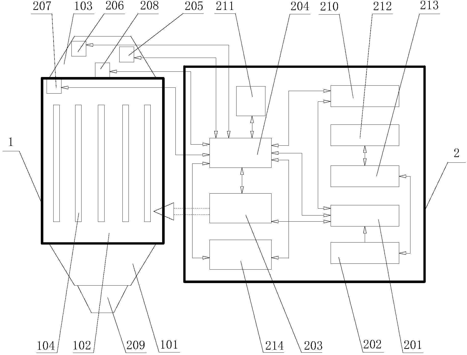
[0021] Example: see figure 1 , a vertical microwave photo-oxygen catalytic exhaust gas purifier, including a reaction unit 1 and a control unit 2, the control unit 2 includes an automatic control unit 2 of PLC204, a microwave generation unit 203, a waste water collection and discharge unit, an ozone detection unit, a VOC The detection unit and the fault self-inspection unit 211 also include a power supply module that provides energy for the purifier, and the reaction unit 1 includes an air inlet 101, a reaction chamber 102 and an exhaust port 103; the reaction chamber 102 is a built-in There is a vertical cavity with a lamp tube 104, its lower part is an air inlet 101, and the upper part is an air outlet 103, and the air inlet 101, the air outlet 103 and the reaction chamber 102 are on the same central axis; the ozone monitoring The unit 205 , the probe of the VOC monitoring unit 206 , and the waste water collection unit 209 are all set in the reaction unit 1 and connected to ...


PUM


Abstract

The invention discloses a vertical microwave photo-oxidative catalytic waste gas purifier which comprises a reaction unit and a control unit, wherein the control unit comprises a PLC automatic control unit, a microwave generation unit, a wastewater collection and discharge unit, an ozone detection unit, a VOC detection unit, a fault self-detection unit and a power module which is used for providing energy to the purifier; a gas inlet, a reaction cavity and a gas outlet are formed in the reaction unit; the reaction cavity is a vertical cavity in which a lamp tube is arranged; the gas inlet is arranged below the reaction cavity and the gas outlet is arranged above the reaction cavity; the gas inlet, the gas outlet and the reaction cavity are located on a same axle wire. Through the vertical reaction cavity, the gas inlet, the gas outlet and the reaction cavity are located on the same axle wire, so that the flowing direction of the gas does not deflect, the windage is reduced to the greatest extent, the gas flow is smoother and the operating energy consumption of the equipment is reduced; washing can be carried out from the top to bottom, so that the water efficiency is high, the wastewater is conveniently discharged to prevent waterlogging, and the humidity in the reaction cavity is reduced.

Description

technical field [0001] The invention relates to the field of organic waste gas purification, in particular to a vertical microwave photo-oxygen catalytic waste gas purifier. Background technique [0002] The main purification principle of the existing photoelectric, photo-oxygen, photocatalytic and other organic waste gas purifiers on the market is basically to use ultraviolet light to generate ozone, and then use the strong oxidative properties of ozone to oxidize and decompose the waste gas to decompose and convert the toxic and odorous macromolecular waste gas Generate non-toxic and tasteless small molecular substances such as carbon dioxide, water and so on. [0003] The existing photoelectric, photo-oxygen, photocatalytic and other exhaust gas purifiers on the market basically have the following defects: [0004] 1. The equipment has a low tolerance to the humidity of the exhaust gas, and the relative humidity must be less than 60%; [0005] 2. The temperature toleran...

Claims


Application Information

Patent Timeline
IPC IPC(8): B01D53/86
Inventor 张雷代秀琼代桂香宋强
Owner 四川蓝雨禾环保科技有限公司
Learn More