Inner and outer circumference welding machine for cylinder

A technology of cylindrical and ring welding machines, applied in welding equipment, welding equipment, welding accessories, etc., can solve the problems of uneven solder, high labor intensity of operators, unqualified welding quality, etc., and achieve simple equipment structure design, The equipment has a wide range of applications and the effect of adjustable wire feeding speed

Active Publication Date: 2015-01-21
杭州润德车轮制造有限公司
View PDF3 Cites 31 Cited by
  • Summary
  • Abstract
  • Description
  • Claims
  • Application Information

AI Technical Summary

Problems solved by technology

[0002] Surround welding on the outer surface of a cylindrical workpiece generally relies on manual welding by electric welders. During manual welding, the welding quality is unstable, the solder is uneven, and there are often too many solders in local areas or too little solder in local areas. If it is unqualified, it will increase the difficulty of post-processing, consume too much labor, time, and energy, use a lot of solder, and waste materials. When manual welding, the labor intensity of the operator is not conducive to the improvement of production efficiency, and is not conducive to the reduction of production costs. control
[0003] And for the cylindrical workpiece with high bearing strength, such as the connection between engineering rim rim body and lock groove ring, the connection of two cylinders, etc., in order to ensure the strength, its inner and outer surfaces all need to be welded. The automatic welding machine of the prior art Generally, there is only one welding torch or two welding torches that weld the outer surface at the same time. This kind of automatic welding machine cannot realize the simultaneous welding of the inner and outer peripheral surfaces of the cylindrical workpiece, and the welding efficiency is low and the welding quality is poor.

Method used


Image

  • Inner and outer circumference welding machine for cylinder
  • Inner and outer circumference welding machine for cylinder
  • Inner and outer circumference welding machine for cylinder

Examples


Embodiment Construction

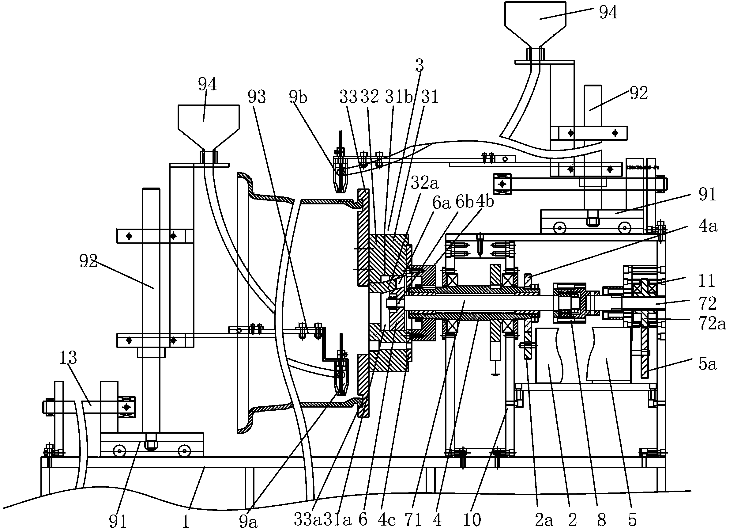
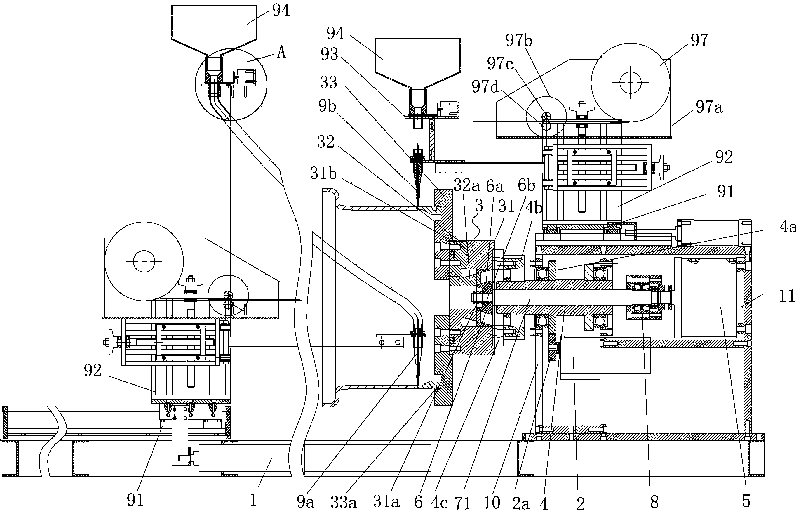
[0035] figure 1 Shown is the structural diagram of the cylindrical internal and external circumferential welding machine of the first embodiment of the present invention (the welding torch feeding device, welding wire feeding mechanism and position adjustment mechanism are not shown in the figure), figure 2 Shown is a structural diagram of a cylinder inner and outer girth welding machine according to the second embodiment of the present invention. Depend on figure 1 , figure 2 It can be seen that the cylindrical internal and external circumferential welding machine of the present invention includes: a power device 2, which is placed on the base 1; a clamp 3 for clamping the cylinder to be welded is connected with the power device 2 through a transmission mechanism, so that the power device 2 Driven by the device 2, the cylinder to be welded is driven to rotate; the inner and outer torches 9a, 9b are placed on the base 1, respectively located on the inside and outside of th...


PUM


Abstract

The invention discloses an inner and outer circumference welding machine for a cylinder. The inner and outer circumference welding machine is characterized by comprising a power device (2) mounted on a base (1), a clamp (3), an inner welding gun and an outer welding gun (9a and 9b), wherein the clamp (3) is used for clamping a cylinder and connected with the power device (2) through a transmission mechanism to bring convenience for driving the cylinder to rotate under driving of the power device; the inner welding gun and the outer welding gun (9a and 9b) are respectively arranged on the base through a welding gun support device, respectively positioned on the inner side and the outer side of the cylinder and aligned with the same circumferential weld on the cylinder to bring convenience for welding the inner side and the outer side of the circumferential weld when the cylinder rotates. The inner and outer circumference welding machine can achieve girth welding of the inner circumferential surface and the outer circumferential surface of the cylinder at the same time, the weld quality is good, workpieces can be mounted and dismounted very conveniently, and the welding speed can be controlled to meet the requirements for welding different workpieces.

Description

technical field [0001] The invention relates to a ring welding machine, in particular to a ring welding machine capable of simultaneously welding the inner and outer peripheral surfaces of a cylindrical body. Background technique [0002] Surround welding on the outer surface of a cylindrical workpiece generally relies on manual welding by electric welders. During manual welding, the welding quality is unstable, the solder is uneven, and there are often too many solders in local areas or too little solder in local areas. If it is unqualified, it will increase the difficulty of post-processing, consume too much labor, time, and energy, use a lot of solder, and waste materials. When manual welding, the labor intensity of the operator is not conducive to the improvement of production efficiency, and is not conducive to the reduction of production costs. control. [0003] And for the cylindrical workpiece with high bearing strength, such as the connection between engineering ri...

Claims


Application Information

Patent Timeline
Patent Type & Authority Applications(China)
IPC IPC(8): B23K9/02B23K9/32B23K37/053B23K37/00
CPCB23K9/0282B23K9/32B23K37/00B23K37/053
Inventor 许奇
Owner 杭州润德车轮制造有限公司
Why Eureka
Try Eureka