
Jig for drilling of circular shaft

A fixture and round shaft technology, applied in the field of round shaft drilling fixtures, can solve the problem of only one processing, and achieve the effects of stable clamping, simple structure and convenient use.

Active Publication Date: 2015-01-21
SUZHOU SUTENG ELECTRONICS TECH
View PDF7 Cites 3 Cited by
  • Summary
  • Abstract
  • Description
  • Claims
  • Application Information

AI Technical Summary

Problems solved by technology

This equipment improves the processing accuracy, but it can only process one piece at a time, and only one length of round shaft parts can be processed.

Method used


Image

  • Jig for drilling of circular shaft
  • Jig for drilling of circular shaft
  • Jig for drilling of circular shaft

Examples


Embodiment Construction

[0017] The present invention will be further described below in conjunction with the accompanying drawings. The following examples are only used to illustrate the technical solution of the present invention more clearly, but not to limit the protection scope of the present invention.

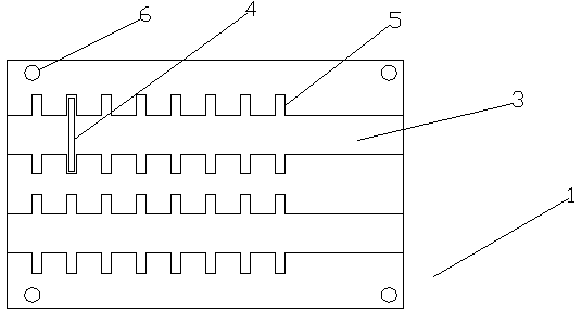
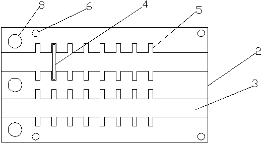
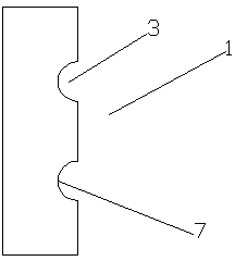
[0018] As shown in the figure, a jig for circular shaft drilling according to the present invention includes an upper jig 1 and a lower jig 2 used in conjunction, and the corresponding positions of the upper jig 1 and the lower jig 2 are provided with semicircular through grooves 3 , one side of the semicircular through groove 3 is provided with a baffle 4, the baffle 4 is inserted into the lower fixture 2 through the slot 5 on the lower fixture 2, and there are a plurality of the slots 5, which are arranged in parallel on the lower fixture 2, and perpendicular to the semicircular through groove 3, the position corresponding to the lower clamp 2 on the upper clamp 1 is also provided with a card ...


PUM


Abstract

The invention discloses a jig for drilling of a circular shaft. The jig for the drilling of the circular shaft comprises an upper jig and a lower jig which are used cooperatively, and is characterized in that two semicircular through grooves are respectively formed in portions of the upper jig and the lower jig, which are corresponding, a baffle is arranged on the same side of the semicircular through grooves, the baffle is inserted into the lower jig through clamp grooves in the lower jig, the number of the clamp grooves is more than one, the clamp grooves are formed in the lower jig in parallel mode, and vertical to the semicircular through grooves, another clamp groove is further formed in a portion of the upper jig, corresponding to the clamp grooves in the lower jig, two thread holes are respectively formed in edges of the upper jig and the lower jig in corresponding mode, and a bolt passes through the upper jig and the lower jig, and clamps the upper jig with the lower jig by cooperating with a nut. The jig for the drilling of the circular shaft is simple in structure and stable in clamping, achieves a fixing function in the radial direction of the circular shaft by using the upper jig cooperatively with the lower jig, achieves a fixing function for an axial device of the circular shaft through the baffle, and thereby clamps the circular shaft.

Description

technical field [0001] The invention relates to a clamp, in particular to a clamp for circular shaft drilling. Background technique [0002] Round shaft parts are common parts in the machining industry. They are cylindrical in shape, have various specifications, and are mostly made of steel. Drill various joint holes. These holes need to be processed by ordinary vertical radial drilling machine. Due to the different lengths of the short shaft parts, it is necessary to constantly replace the fixture during processing, which consumes manpower and leads to low drilling efficiency. [0003] The application number is 201020285919.7 "Circumferential Drilling Equipment for Circular Shaft Parts", which discloses a circular drilling equipment for circular shaft parts. A disk is arranged on the body, and a long bolt is arranged in the disk, a compression nut is arranged on the left side of the long bolt, and an indexing positioning pin is arranged on the disk. This equipment improv...

Claims


Application Information

Patent Timeline
Patent Type & Authority Applications(China)
IPC IPC(8): B23Q3/06
CPCB23Q3/061B23Q3/064
Inventor 周天毫
Owner SUZHOU SUTENG ELECTRONICS TECH
Learn More