
Heat stamping apparatus used for quenching control

A technology of hot stamping and hot stamping die, which is applied in the field of hot stamping, can solve the problem of uniform distribution of surface temperature of formed parts, and achieve the effect of uniform distribution

Inactive Publication Date: 2015-01-21
JIANGSU UNIV
View PDF8 Cites 4 Cited by
  • Summary
  • Abstract
  • Description
  • Claims
  • Application Information

AI Technical Summary

Problems solved by technology

[0008] The purpose of the present invention is to solve the problem that in the hot stamping technology, it is difficult to take into account the uniform distribution of the surface temperature of the formed parts under the condition of ensuring the uniformity of quenching during the quenching process of high-temperature formed parts, and proposes a hot stamping method for hot stamping quenching control. device; it can monitor the temperature value of the selected measuring point in real time during the high-temperature sheet metal forming process, and obtain the quenching rate of the selected measuring point and the temperature difference between them through data processing; when the quenching rate does not meet the conditions or the temperature difference is too large , the control system will adjust the contact pressure between the formed part and the die surface and the cooling water flow rate according to the trigger conditions, so that the quenching rate of the high-temperature formed part meets the requirements and the temperature of the formed part is balanced, thus ensuring the final formed part. Strength quality requirements and forming accuracy requirements

Method used


Image

  • Heat stamping apparatus used for quenching control
  • Heat stamping apparatus used for quenching control
  • Heat stamping apparatus used for quenching control

Examples


Embodiment approach

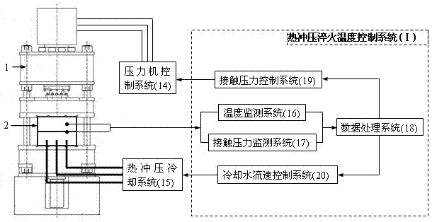
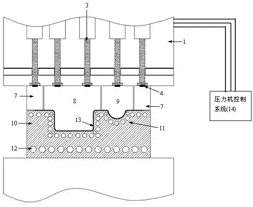
[0031] Such as figure 1 As shown, a hot stamping quenching temperature control system of the present invention and its supporting pressure control device are mainly composed of a servo press 1, a press control system 14, a hot stamping cooling system 15, a hot stamping die 2 and a hot stamping press The quenching temperature control system I is composed; the hot stamping quenching temperature control system I includes a temperature monitoring system 16, a contact pressure monitoring system 17, a data processing system, a contact pressure control system 19 and a cooling water flow rate control system 20.

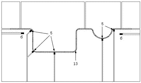
[0032] Such as figure 2 As shown, taking a specific shaped part as an example to illustrate the arrangement of relevant thermocouples;

[0033] The thermocouple 5 used to measure the temperature of the formed part 13, because the highest temperature point and the lowest temperature point in the formed part 13 must be measured, and the bottom surface of the characteristic st...


PUM


Abstract

The invention provides a heat stamping apparatus used for quenching control, which belongs to the technical field of heat stamping. A purpose of the present invention is to solve the problems that in a heat stamping technology, in the quenching process of a high-temperature forming part, uniform distribution of surface temperature of the forming part can not be guaranteed on the condition that quenching uniformity is guaranteed, and the invention provides the heat stamping apparatus used for heat stamping quenching control. The heat stamping apparatus enables real time monitoring on the temperature value of selected measurement points during a high-temperature plate shaping process, the quenching rate and temperature difference between the selected measurement points can be obtained through data processing; when the quenching rate can not satisfy the condition or the temperature difference is large, a control system is capable of adjusting contact pressure and cooling water flow velocity of the forming parts and mold surface with pertinence according to the trigger condition, then the quenching rate of the high-temperature forming parts can satisfy the requirement, and the temperature of the forming parts can be equalized, so that the intensity quality requirement and the forming precision requirement of the final forming parts can be ensured.

Description

technical field [0001] The invention provides a hot stamping device for quenching control, which belongs to the technical field of hot stamping. Background technique [0002] The use of ultra-high-strength steel plates to form body parts is an effective means to reduce the weight of the car body. However, the traditional cold stamping technology is unable to cope with the high strength and low elongation of ultra-high-strength steel plates at room temperature. Therefore, hot stamping technology emerged as the times require. , which can solve the limitations of the formability of ultra-high-strength steel plates at room temperature. [0003] Hot stamping technology is an advanced manufacturing technology for forming ultra-high-strength parts. Its principle is to heat ultra-high-strength steel plates or pre-formed ultra-high-strength parts to above 950°C, and send them to the Forming in a special mold, and quenching the mold after holding the pressure for a period of time. At...

Claims


Application Information

Patent Timeline
IPC IPC(8): C21D1/673C21D11/00
CPCC21D1/673C21D11/00
Inventor 陈炜陈泷李建东张欢衡思宁吴甲沈烺楠
Owner JIANGSU UNIV
Learn More