A pneumatic motor with screw drive

A pneumatic engine and screw rod technology, applied in the direction of machines/engines, intermeshing engines, mechanisms for generating mechanical power, etc., can solve problems such as low energy utilization rate, low output power, and temperature drop, and improve energy utilization efficiency , Improve the effect of energy utilization

Inactive Publication Date: 2016-08-24
TAIYUAN UNIV OF TECH
View PDF5 Cites 0 Cited by
  • Summary
  • Abstract
  • Description
  • Claims
  • Application Information

AI Technical Summary

Problems solved by technology

However, the pure pneumatic engine working fluid expands and absorbs heat, which causes the temperature of the cylinder wall, cylinder head and other components to drop, and even frost, which has the disadvantages of low output power and low energy utilization rate.
[0004] Most of today's pneumatic vehicles use piston-type pneumatic engines. The compressed air expands in the cylinder to push the piston to do work, and the return exhaust is exhausted under the action of the inertial force of the crankshaft and flywheel. Every time the compressed air expands to do work, it must overcome the atmospheric pressure or even higher. pressure, high energy consumption

Method used


Image

  • A pneumatic motor with screw drive
  • A pneumatic motor with screw drive
  • A pneumatic motor with screw drive

Examples


Embodiment

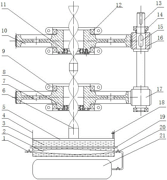
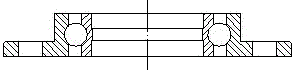
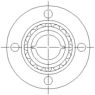
[0030] Such as Figure 1~3 as shown,

[0031] A pneumatic engine adopting screw rod transmission, including an air storage tank 21, an expansion air bag 2, a cylinder 4, a piston 5, a heat exchange fluid 3, a bearing, a gear, a screw rod 6, and an output shaft 13; the inside of the cylinder 4 is provided with The expansion air bag 2 and the cylinder 4 are equipped with heat exchange fluid 3, the expansion air bag 2 is located between the heat exchange liquid 3, the piston 5 is arranged above the heat exchange liquid 3, the center of the piston 5 is connected to the screw rod 6, and the two ends of the screw rod 6 The spiral direction is opposite, the lower end of the screw rod 6 is provided with a first one-way bearing 8, the upper end of the screw rod 6 is provided with a second one-way bearing 11, and the left end of the first one-way bearing 8 is connected to the first gear 7, and the first gear 7 is connected to the first gear 7. A pair of ball bearings 9 are positioned i...


PUM


Abstract

The invention discloses a pneumatic engine adopting a spiral rod for transmission and belongs to the field of new-energy pneumatic engines. The device comprises two parts, namely a spiral rod transmission mechanism and a large-bore cylinder, wherein the spiral rod transmission mechanism is positioned above the cylinder, the spiral rod transmission mechanism comprises the spiral rod with opposite rotation directions of threads at the two ends, a gear, a one-way bearing, a bolt, an inner ring of the one-way bearing contacts an external thread of the spiral rod, an outer ring of the one-way bearing is fixed on the side end surface of the gear by the bolt, the spiral rod is subjected to the push-pull motion of a piston, and the upward and downward movements of the spiral rod act on the gear through the one-way bearing respectively to do work against an output shaft. The pneumatic engine disclosed by the invention reduces the influence of pressure changes in a gas storage tank on output of the engine, simultaneously utilizes atmospheric pressure to do work, and upgrades the energy utilization rate of compressed air, so that economy and efficiency of the pneumatic engine are improved.

Description

technical field [0001] The invention relates to a pneumatic motor driven by a screw rod, which belongs to the field of new energy pneumatic motors. Background technique [0002] The emergence of the internal combustion engine has greatly promoted the progress of human society. However, with the rapid entry of cars into ordinary people's homes, energy issues and environmental issues have become increasingly prominent. Countries in the world have begun and have achieved results in the field of new energy vehicles. Our country has already had electric vehicles and hybrid vehicles. It has the achievement of independent intellectual property rights, but it has just started in the research and development of pneumatic vehicles powered by compressed air. [0003] Pneumatic engine refers to the use of compressed air or liquid nitrogen as a power source to drive the car, which can be said to be a zero-emission car. However, the expansion and heat absorption of the working medium of...

Claims


Application Information

Patent Timeline
Patent Type & Authority Patents(China)
IPC IPC(8): F01C1/16
CPCF03G7/06
Inventor 郭文亮孙瑞光张杰韩念琛朱建军郭政崔建伟徐灵源
Owner TAIYUAN UNIV OF TECH
Why Eureka
Try Eureka