Waste lubricating grease collecting structure of wind driven generator spindle bearing

A technology for wind turbines and waste lubricating oil, which is applied in the direction of engine lubrication, engine components, lubricating parts, etc., and can solve waste lubricating grease fires, insufficient replacement of new lubricating grease and waste lubricating grease, wind turbine pollution, etc. question

Active Publication Date: 2015-01-21
欣达重工股份有限公司
View PDF7 Cites 6 Cited by
  • Summary
  • Abstract
  • Description
  • Claims
  • Application Information

AI Technical Summary

Problems solved by technology

Among them, the waste oil recovery device is generally an oil collection bottle fixed on the main shaft, but since the oil collection bottle is in a static state and the recovery oil path between the oil collection bottle and the movable cavity of the bearing roller will be relatively long, so in the automatic supply When the oil device supplies new lubricating grease to the movable cavity of the bearing roller, the waste lubricating grease in the movable cavity of the bearing roller has not been recovered in time, resulting in insufficient replacement of new lubricating grease and waste lubricating grease. The accumulation of waste lubricating grease will cause excessive oil pressure to form an impact on the skeleton sealing ring, resulting in failure of the oil seal, causing waste lubricating grease to overflow from the sealing structure, causing pollution to the wind turbine, and in serious cases, the overflowing waste lubricating grease will be ignited resulting in fires and significant economic losses

Method used


Image

  • Waste lubricating grease collecting structure of wind driven generator spindle bearing
  • Waste lubricating grease collecting structure of wind driven generator spindle bearing
  • Waste lubricating grease collecting structure of wind driven generator spindle bearing

Examples


Embodiment 1

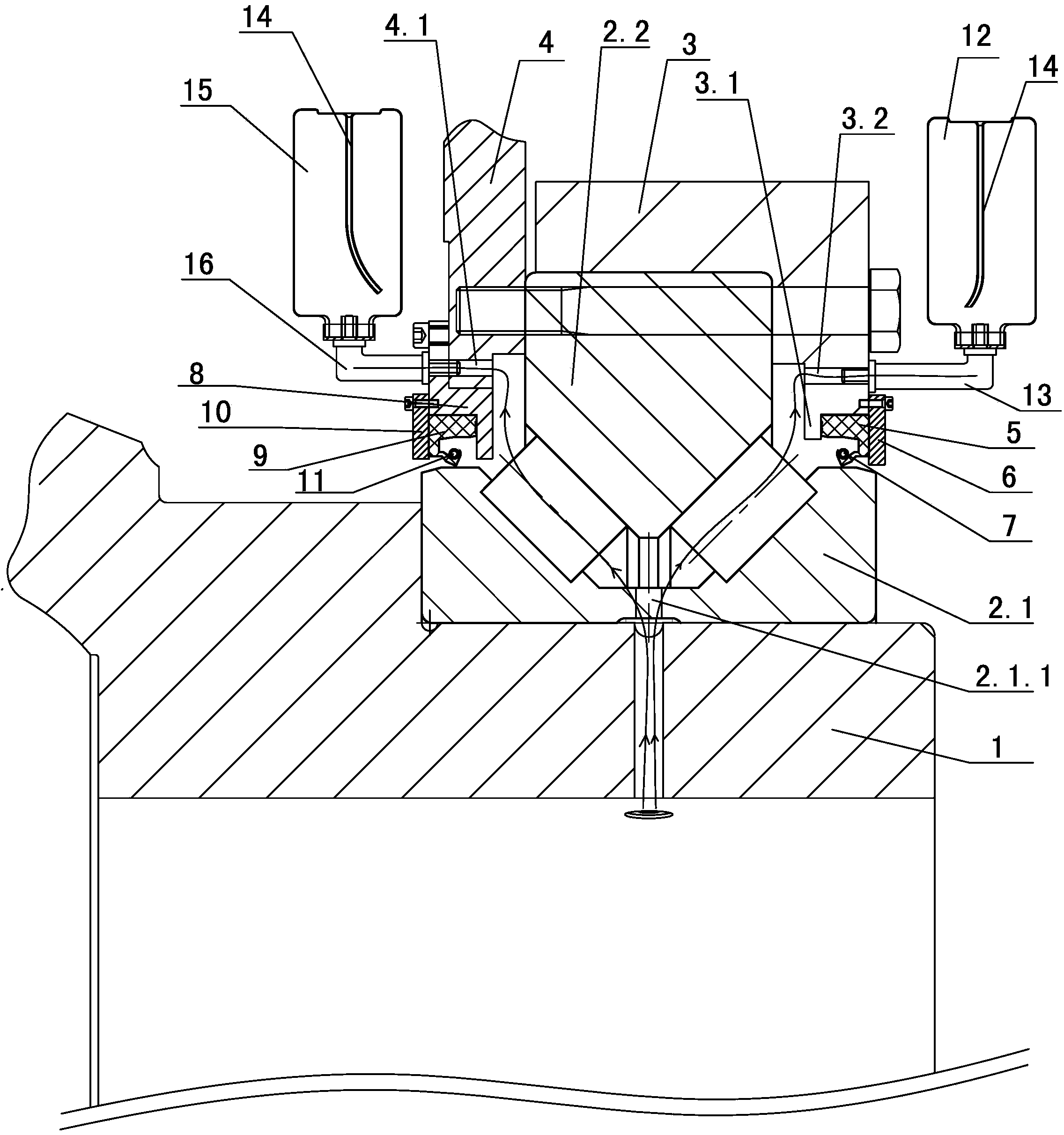
[0019] The collection structure of the main shaft bearing waste lubricating grease of embodiment 1 is as follows figure 1 As shown, the bearing inner ring 2.1 is fixed to the main shaft 1, the turntable 3 and the rotor 4 are respectively fixed on both sides of the bearing outer ring 2.2 by a plurality of bolts, a first sealing structure is provided between the turntable 3 and the bearing inner ring 2.1, and the rotor 4 There is a second sealing structure between the bearing inner ring 2.1.1, the first sealing structure and the second sealing structure are used to seal the oil in the movable cavity of the bearing roller, and the bearing inner ring 2.1 is provided with a communication oil supply device (Fig. Not shown in ) and the oil inlet hole 2.1.1 of the roller movable cavity; also includes the first oil collection assembly and the second oil collection assembly; the first oil collection assembly includes the first oil collection bottle 12 and the first oil passage pipe 13. ...

Embodiment 2

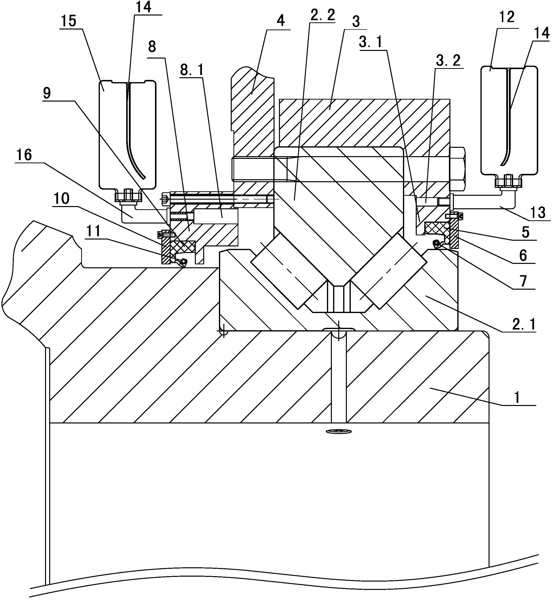
[0024] The first sealing structure and the first oil collecting assembly in embodiment 2 are the same as the first sealing structure and the first oil collecting assembly in embodiment 1, except that figure 2 As shown: 1. The second sealing structure includes a sealing seat 8, a second skeleton sealing ring 9 with a "V"-shaped opening facing the roller movable cavity, and a second sealing cover 10; the sealing seat 8 is fixed to the rotor 4 , the second sealing cover plate 10 is fixed to the sealing seat 8, the second skeleton sealing ring 9 is fixedly installed in the cavity surrounded by the sealing seat 8, the main shaft 1 and the second sealing cover 10, the second skeleton sealing ring 9 The opening is provided with a second spring fastening ring 11 for ensuring the sealing fit between the second skeleton sealing ring 9 and the main shaft 1 . 2. The second oil collection assembly includes a second oil collection bottle 15 and a second oil passage pipe 16. The second oil ...

Embodiment 3

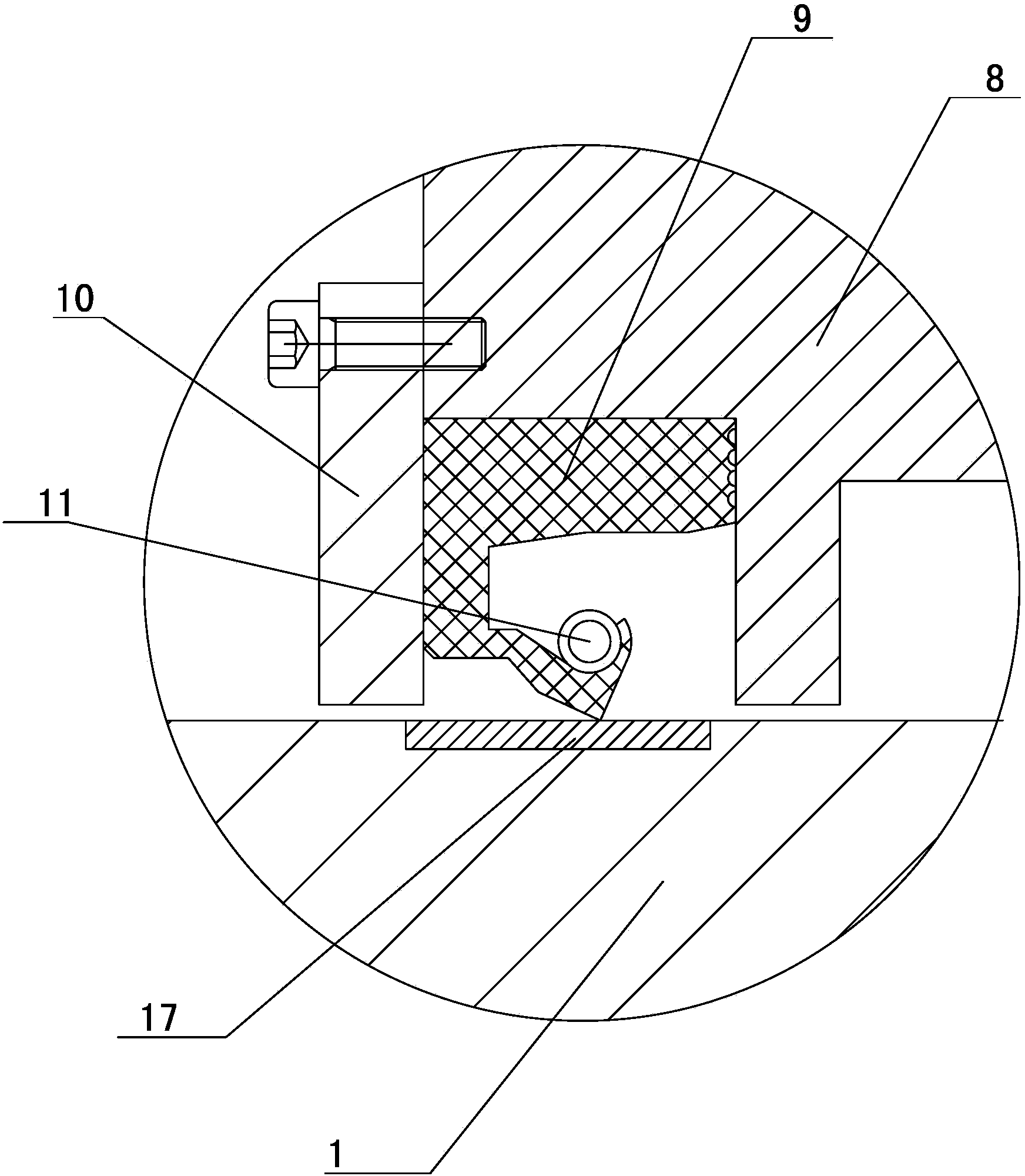
[0025] The first sealing structure, the first oil collecting assembly and the second oil collecting assembly in embodiment 3 are the same as the first sealing structure, the first oil collecting assembly and the second oil collecting assembly in embodiment 2, except that image 3 As shown: the second sealing structure includes a sealing seat 8, a second skeleton sealing ring 9 with a "V"-shaped opening facing the movable cavity of the roller, a second sealing cover plate 10 and an annular wear-resistant ring fixed on the main shaft 1 Steel belt 17; the sealing seat 8 is fixed to the rotor 4, the second sealing cover 10 is fixed to the sealing seat 8, and the second skeleton sealing ring 9 is fixedly installed on the sealing seat 8, the annular wear-resistant steel belt 17 and the second sealing cover In the cavity surrounded by 10, the opening of the second skeleton sealing ring 9 is provided with a second spring fastening ring 11 for ensuring the sealing fit between the second...


PUM


Abstract

The invention discloses a waste lubricating grease collecting structure of a wind driven generator spindle bearing. The waste lubricating grease collecting structure of the wind driven generator spindle bearing has the advantages that a first grease collecting bottle is fixed to a turntable through a first grease delivery pipe and is communicated with a roller moving cavity through the first grease delivery pipe and a first grease outlet in the turntable, and a second grease collecting bottle is fixed to a rotor through a second grease delivery pipe and communicated with the roller moving cavity through the second grease delivery pipe and a second grease outlet in the rotor. A grease collecting pipeline is shortened, air in the grease collecting bottles is easily exhausted and can produce certain suction force under the effect of centrifugal force due to the fact that the first grease collecting bottle and the second grease collecting bottle are installed on the turntable and the rotor respectively, waste lubricating grease can timely flow into the grease collecting bottles, and accordingly when a grease supply device supplies new lubricating grease, the new lubricating grease can well extrude the waste lubricating grease, and the waste lubricating grease can be fully replaced by the new lubricating grease.

Description

technical field [0001] The invention relates to a recovery device for waste lubricating grease, in particular to a collection structure for waste lubricating grease of a main shaft bearing of a wind power generator. Background technique [0002] In the early 1970s, due to the "oil crisis", there was a problem of energy shortage. People realized the instability and limitation of conventional mineral energy supply, so the search for clean and renewable energy has become an important issue in the modern world. Wind energy as Renewable, pollution-free natural energy has attracted people's attention. [0003] A wind turbine is a power machine that converts wind energy into mechanical work. Existing wind power generators mainly include a generator, wind blades and a main shaft. The rotating disk of the wind blades and the rotor of the generator are fixed to the main shaft through bearings. The first sealing structure of the turntable and the inner ring of the bearing on one sid...

Claims


Application Information

Patent Timeline
Patent Type & Authority Applications(China)
IPC IPC(8): F16N31/02
Inventor 陈朝富张水龙
Owner 欣达重工股份有限公司
Why Eureka
Try Eureka