Heat exchanger

A technology of heat exchangers and heat exchange tubes, applied in evaporators/condensers, lighting and heating equipment, refrigeration components, etc., can solve the problem of reducing cooling heat exchange capacity and heat exchange performance, small effective heat exchange area, and frosting Fast speed and other issues, to achieve the effect of improving the cooling capacity and heat transfer performance, increasing the effective heat transfer area, and reducing the water storage

Active Publication Date: 2015-01-21
SANHUA HANGZHOU MICRO CHANNEL HEAT EXCHANGER
View PDF6 Cites 8 Cited by
  • Summary
  • Abstract
  • Description
  • Claims
  • Application Information

AI Technical Summary

Problems solved by technology

The problem of this kind of heat exchanger is that there is always a large amount of water in the fins below; the drainage stroke is long and the drainage speed is slow, which leads to the rapid frosting and frost formation of the heat exchanger under the condition of outdoor low temperature and high humidity. The amount of frost is too large, the effective heat transfer area is small, which reduces the cooling capacity and heat transfer performance, and increases energy consumption

Method used


Image

  • Heat exchanger
  • Heat exchanger
  • Heat exchanger

Examples


Embodiment Construction

[0025] Embodiments of the invention are described in detail below, examples of which are illustrated in the accompanying drawings. The embodiments described below by referring to the figures are exemplary and are intended to explain the present invention and should not be construed as limiting the present invention.

[0026] Refer below Figure 1-Figure 5 The heat exchanger 100 according to the embodiment of the present invention will be described in detail.

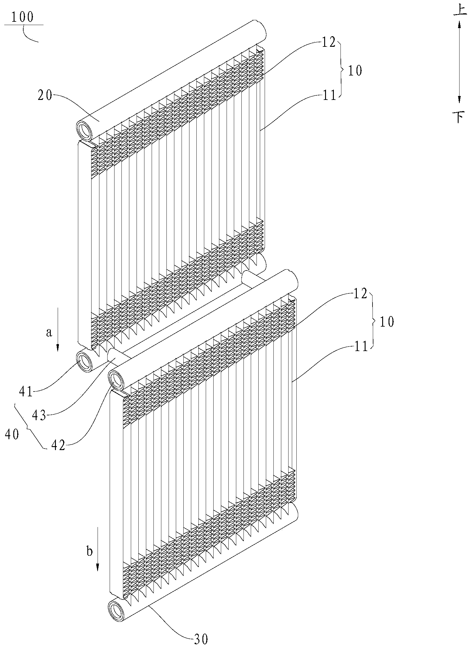
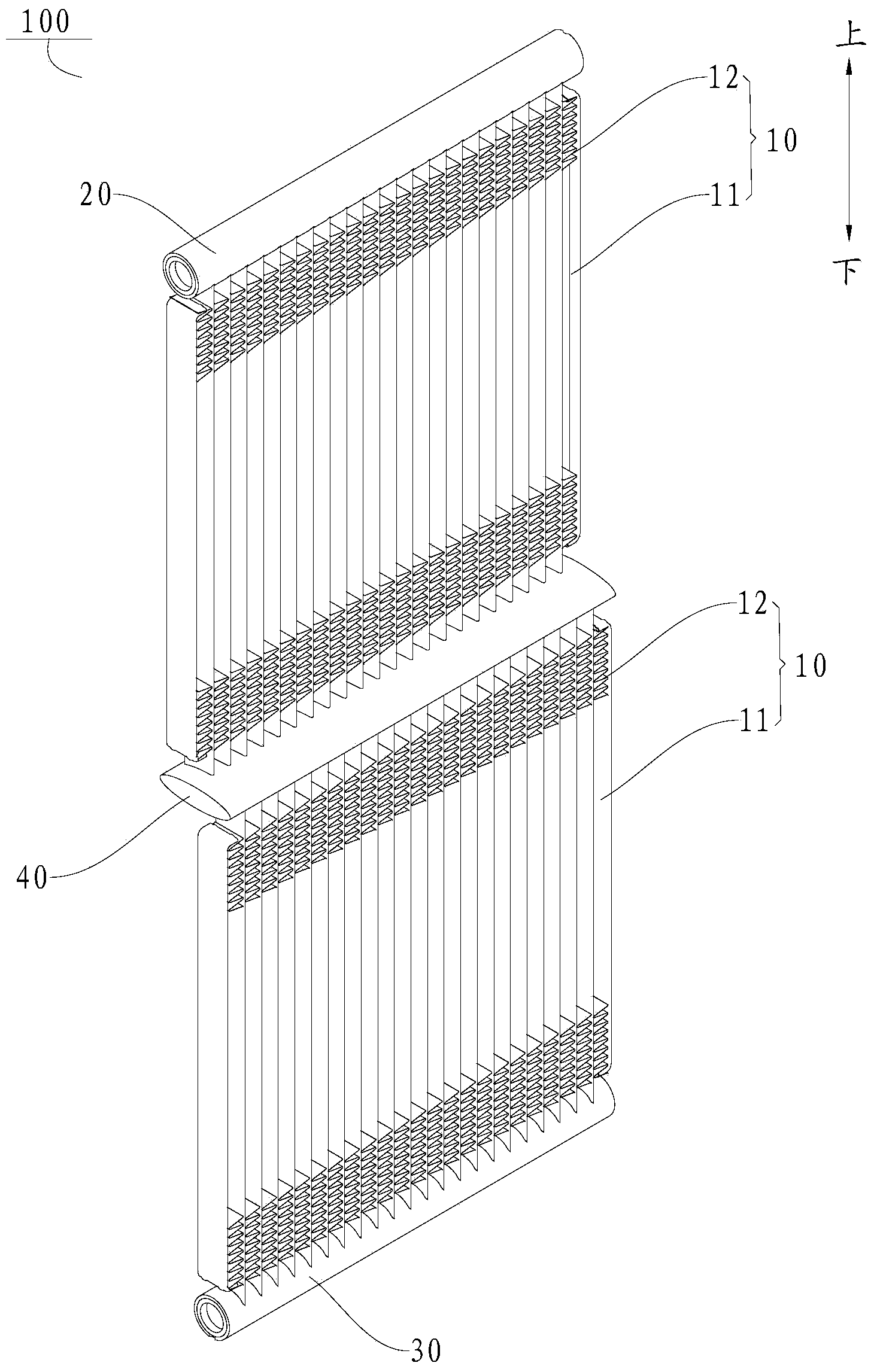
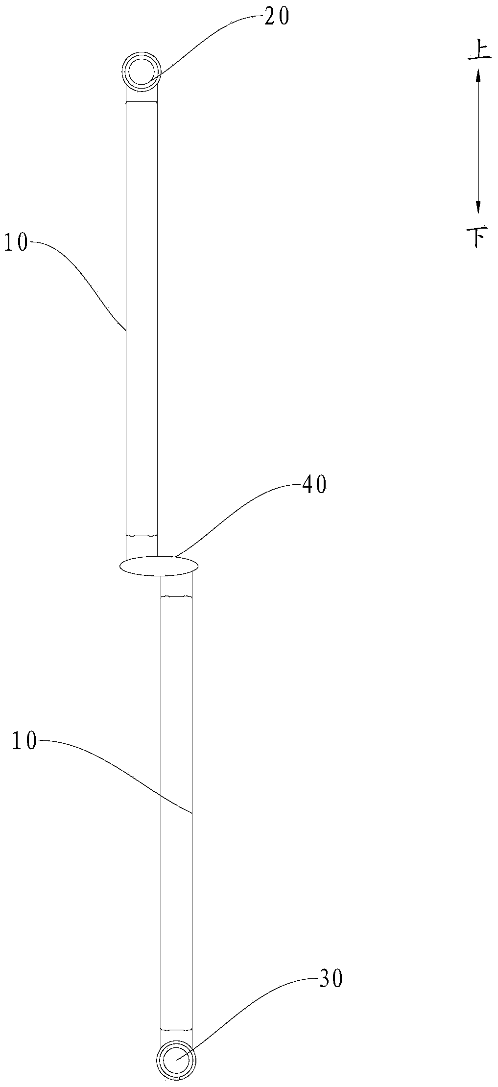
[0027] Such as Figure 1-Figure 5 As shown, the heat exchanger 100 according to the embodiment of the present invention includes: a plurality of heat exchange cores 10 , a first header 20 , a second header 30 and a connecting piece 40 .

[0028] Such as figure 1 As shown, a plurality of heat exchange cores 10 are arranged in the up and down direction, and each heat exchange core 10 includes a plurality of heat exchange tubes 11 and fins 12 arranged between two adjacent heat exchange tubes 11, the heat exchange The tu...


PUM


Abstract

The invention discloses a heat exchanger. The heat exchanger comprises a plurality of heat exchange cores arranged in the vertical direction, a first collecting main, a second collecting main and a communicating piece. A heat exchange pipe of the upper heat exchange core of every two adjacent heat exchange cores is communicated with a heat exchange pipe of the lower heat exchange core through the communicating piece. Every two adjacent heat exchange cores are located in the different planes. Due to the fact that every two adjacent heat exchange cores are located in the different planes, condensate water generated by every two adjacent heat exchange cores flows in the different planes, multiple different drainage paths are provided for drainage of condensate water, the drainage amount borne by each drainage path is greatly reduced, the drainage efficiency of the heat exchanger is improved, the frosting speed of the heat exchanger is effectively reduced under the outdoor low-temperature and high-humidity working condition, the frosting amount is reduced, the refrigeration and heat exchange capacity and the heat exchange performance of the heat exchanger are improved, and energy consumption is reduced.

Description

technical field [0001] The present invention relates to the technical field of heat exchange, in particular to a heat exchanger, especially to a parallel flow heat exchanger such as a multi-channel heat exchanger. Background technique [0002] At present, when a parallel flow heat exchanger such as a multi-channel heat exchanger is used as an evaporator, the condensed water is drained through the fin openings, and the condensed water flows through the fin openings from top to bottom, and then from the last One fin fenestration exits the heat exchanger. The problem of this kind of heat exchanger is that there is always a large amount of water in the fins below; the drainage stroke is long and the drainage speed is slow, which leads to the rapid frosting and frost formation of the heat exchanger under the condition of outdoor low temperature and high humidity. If the amount of frost is too large, the effective heat transfer area is small, which reduces the cooling capacity an...

Claims


Application Information

Patent Timeline
Patent Type & Authority Applications(China)
IPC IPC(8): F25B39/00
CPCF25B39/00
Inventor 夏煌煌高强
Owner SANHUA HANGZHOU MICRO CHANNEL HEAT EXCHANGER
Why Eureka
Try Eureka