Exhaust system and method of vacuum drying chamber

A technology of vacuum drying and exhaust system, which is applied in the field of exhaust system of vacuum drying chamber, which can solve problems such as chamber environmental hazards and overflow, and achieve the effect of reducing environmental hazards

Inactive Publication Date: 2015-01-21
EVERDISPLAY OPTRONICS (SHANGHAI) CO LTD
View PDF7 Cites 3 Cited by
  • Summary
  • Abstract
  • Description
  • Claims
  • Application Information

AI Technical Summary

Problems solved by technology

[0003] The purpose of the present invention is to provide a vacuum drying chamber exhaust system, which is used to solve the problem that some volatile gases with high concentration of dissolved substances

Method used


Image

  • Exhaust system and method of vacuum drying chamber
  • Exhaust system and method of vacuum drying chamber
  • Exhaust system and method of vacuum drying chamber

Examples


Embodiment Construction

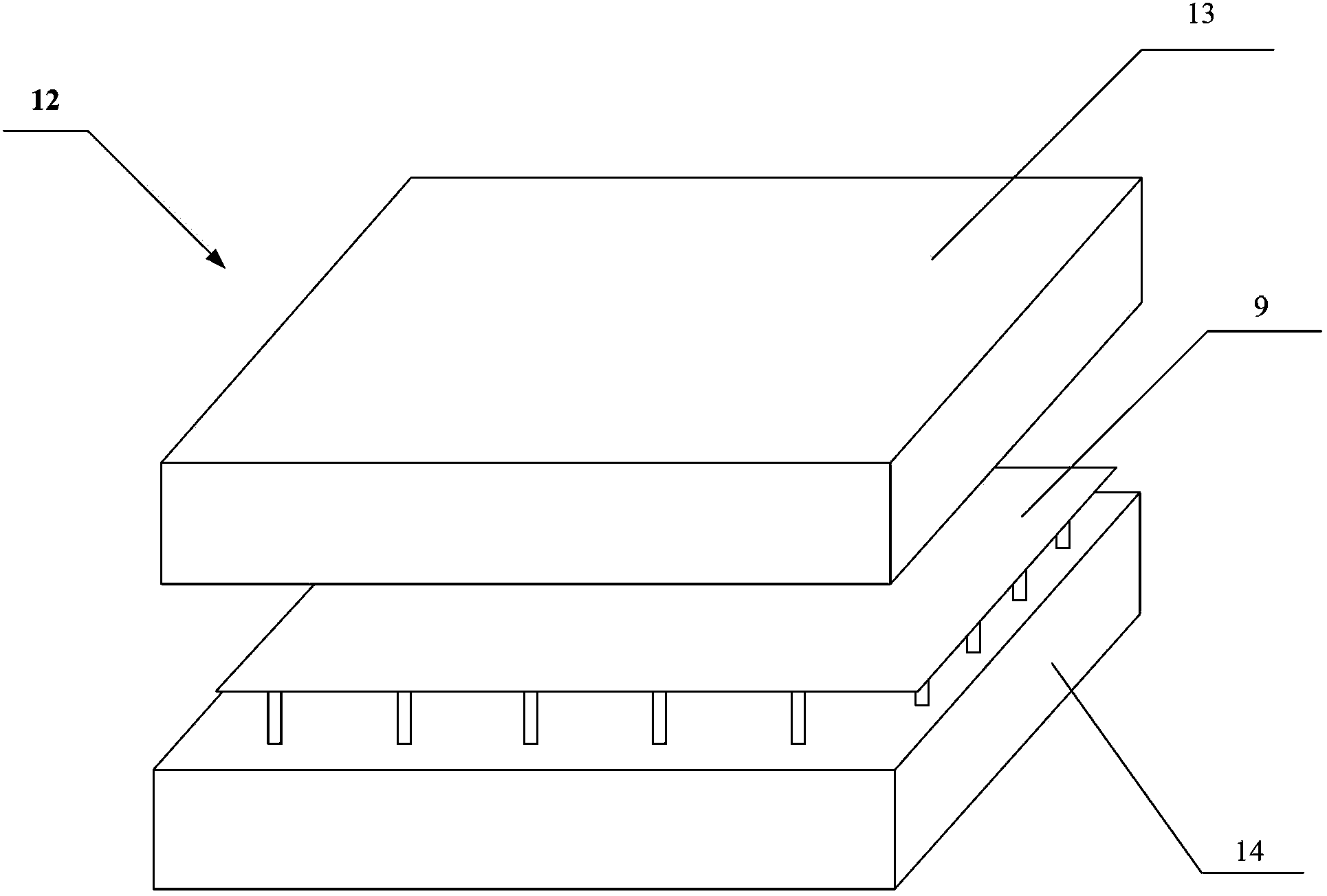
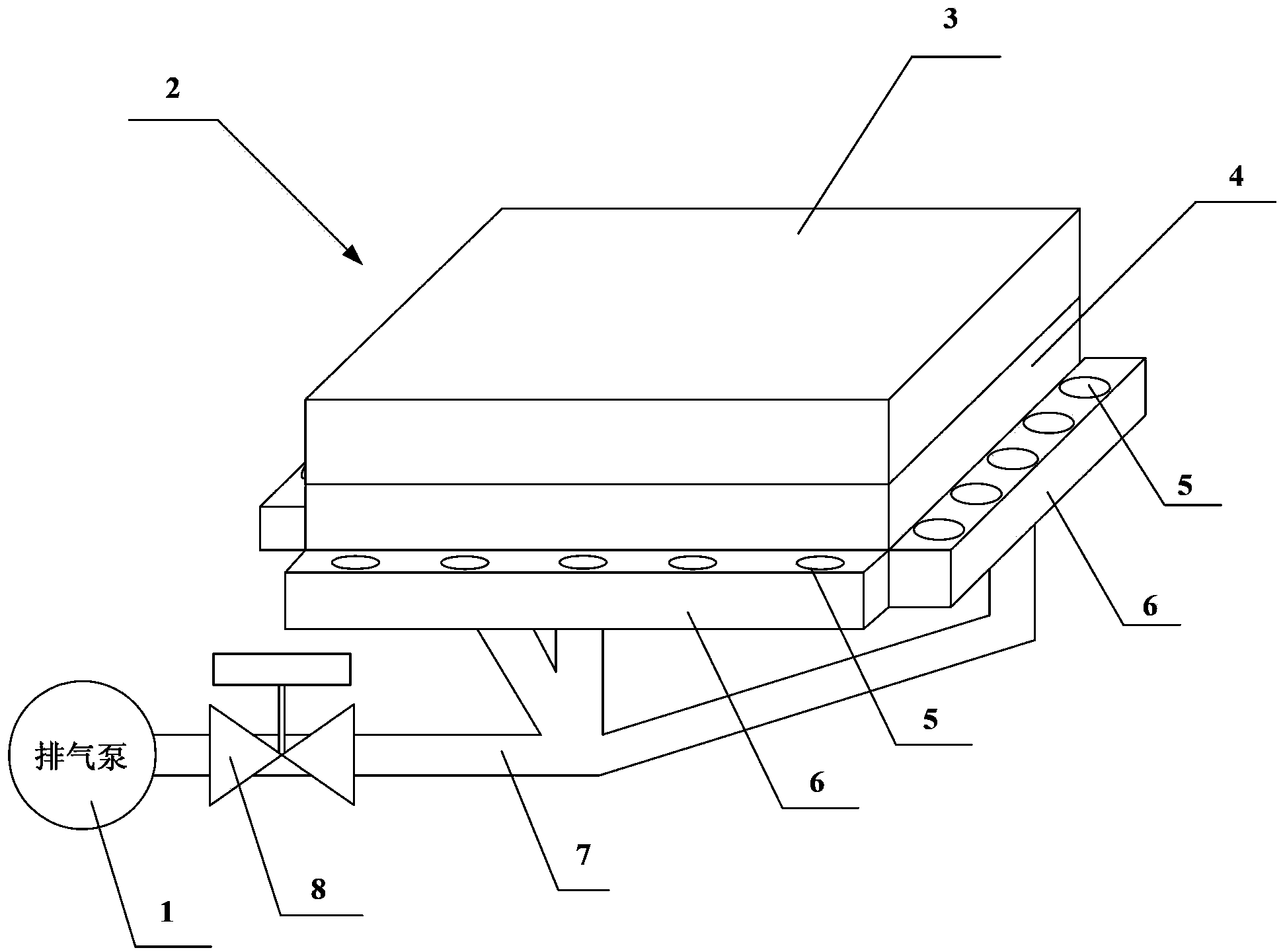
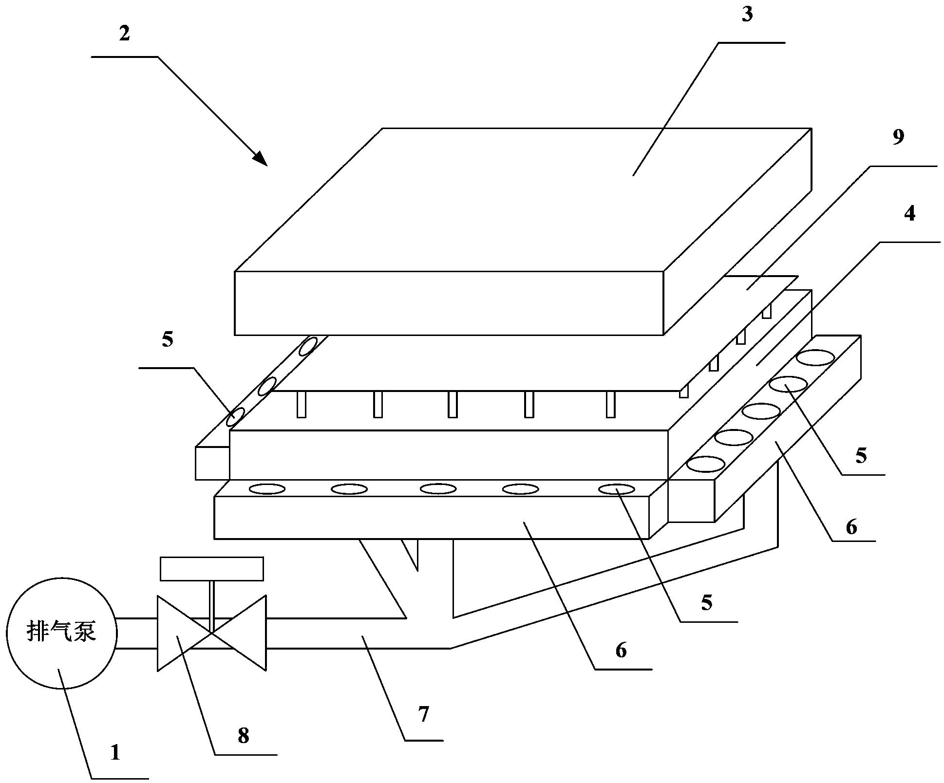
[0023] figure 2 Shown is the schematic diagram of vacuum drying chamber exhaust system of the present invention, as figure 2 As shown, the vacuum drying chamber exhaust system of the present invention includes: a plurality of exhaust ports 5 , an exhaust pump 1 , an exhaust pump valve 8 , a vacuum chamber 2 , an exhaust chamber 6 and an exhaust pipe 7 . The vacuum chamber 2 includes an upper chamber part 3 and a lower chamber part 4 .

[0024] refer to figure 2 , the connection structure of the exhaust system of the vacuum drying chamber in this embodiment is that the exhaust chamber 6 is arranged around the outer side of the lower chamber part 3 of the vacuum chamber 2 . The exhaust cavity 6 is provided with a plurality of exhaust ports 5 . The exhaust cavity 6 is connected with an exhaust pipe 7 , and the exhaust pipe 7 is connected with the exhaust pump 1 . A valve 8 may be arranged on the exhaust pipe 7 to control the on-off of the exhaust pipe 7 .

[0025] For a p...


PUM


Abstract

The invention discloses an exhaust system and method of a vacuum drying chamber. The exhaust system of the vacuum drying chamber comprises a plurality of exhaust openings and an exhaust pump, wherein the exhaust openings are formed outside the vacuum drying chamber; the exhaust pump is connected with the exhaust openings through exhaust pipes. The exhaust method of the vacuum drying chamber includes the steps that when a base plate to be dried is placed in the vacuum drying cavity, exhausting is conducted through the exhaust pump; when the vacuum drying chamber is closed, the exhaust pump is stopped from conducting exhausting; when the dried base plate is taken out of the vacuum drying chamber, exhausting is conducted through the exhaust pump. In conclusion, the multiple exhaust openings are formed outside the vacuum drying cavity, so that when the base plate is stored in and taken out of the cavity, the volatile gas of the dissolved matter of high concentration in the cavity can be discharged through the multiple exhaust openings formed outside the vacuum drying cavity, and the harm to the environment generated in the storing and taking process of the base plate is reduced.

Description

technical field [0001] The invention relates to the technical field of display manufacturing, in particular to an exhaust system and method for a vacuum drying chamber. Background technique [0002] figure 1 Shown is a schematic diagram of an existing vacuum drying chamber, refer to figure 1 , The chamber 12 is composed of an upper chamber 13 and a lower chamber 14 . Generally, the interior of the existing vacuum drying chamber is provided with an exhaust port, which can discharge the volatile gas of the high-concentration dissolved matter in the chamber. However, during the process of taking and placing the substrate 9 in the chamber 12 , some volatile gases of dissolved substances with a high concentration still overflow into the air in the vacuum chamber 12 . As such, there is a hazard to the environment surrounding the chamber. Contents of the invention [0003] The purpose of the present invention is to provide a vacuum drying chamber exhaust system, which is used...

Claims


Application Information

Patent Timeline
IPC IPC(8): F26B25/00
Inventor 黄昱嘉杨靖哲黄正义
Owner EVERDISPLAY OPTRONICS (SHANGHAI) CO LTD
Why Eureka
Try Eureka