A Transformer Sampling Circuit

A technology of sampling circuit and transformer, applied in the direction of instruments, measuring electricity, measuring electrical variables, etc., can solve the problems of loss of leakage current monitoring function, misjudgment of leakage transformers, etc., to facilitate the status of transformers, improve reliability, control handy effect

Active Publication Date: 2017-10-27
HENAN XJ INTELLIGENT CONTROL TECH
View PDF7 Cites 0 Cited by
  • Summary
  • Abstract
  • Description
  • Claims
  • Application Information

AI Technical Summary

Problems solved by technology

[0006] The purpose of the present invention is to provide a transformer sampling circuit to solve the problem of misjudgment of existing leakage transformers, thus losing the monitoring function of leakage current

Method used


Image

  • A Transformer Sampling Circuit
  • A Transformer Sampling Circuit
  • A Transformer Sampling Circuit

Examples


Embodiment Construction

[0015] The present invention will be further introduced below in conjunction with the accompanying drawings and specific embodiments.

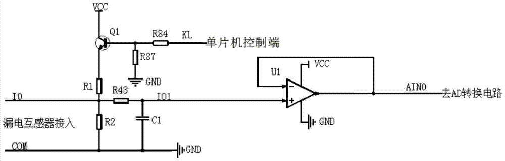
[0016] Such as image 3 Shown is the schematic diagram of the embodiment of the transformer sampling circuit of the present invention. It can be seen from the figure that the circuit includes a sampling resistor R2 arranged between the output terminals (I0, COM) of the secondary side of the transformer, and also includes at least one The open circuit judgment detection circuit formed by the voltage dividing resistor R1 and the switching tube Q1, the sampling resistor R2, the voltage dividing resistor R1 and the switching tube Q1 form a series branch.

[0017] The controller of this embodiment adopts a single-chip microcomputer; the switch tube adopts a triode Q1, the model is 2N3904, the base of the triode Q1 is connected with the control terminal KL of the single-chip microcomputer, its emitter is connected with a voltage dividing resistor, a...


PUM


Abstract

The invention discloses a transformer sampling circuit, which includes a sampling resistor arranged on the output terminal of the secondary side of the transformer, and an open circuit judgment detection circuit composed of at least one voltage dividing resistor and a switch tube. The sampling resistor , the voltage dividing resistor and the switch tube form a series branch. The transformer sampling circuit of the present invention aims at the disadvantages of the connection between the existing electrical fire monitoring detector and the leakage transformer, and adds an online testing circuit to the transformer. The sampling resistor, the voltage dividing resistor and the switching tube form a series branch, and when the current is When 0, the series branch is turned on, and it is judged whether the transformer is open or faulty by detecting the voltage value of the sampling resistor. The circuit structure is easy to control, so that debuggers and users can intuitively understand the status of the line between the leakage transformer and the connection detector, and can accurately display the connection and disconnection of the leakage transformer, which greatly facilitates on-site debugging and monitoring. Master the transformer status during operation.

Description

technical field [0001] The invention relates to a transformer sampling circuit. Background technique [0002] The electrical fire monitoring system belongs to the early pre-alarm system. The difference from the traditional automatic fire alarm system is that the early alarm of the electrical fire monitoring system is to avoid losses, while the traditional automatic fire alarm system is to reduce losses. In order to prevent electrical fires, reduce fire hazards, design electrical fire monitoring systems reasonably, ensure the construction quality and performance of electrical fire monitoring systems, and protect personal and property safety, the "Code for Fire Protection Design of High-rise Civil Buildings" and the mandatory national standard "Residual Current The Installation and Operation of Action Protection Devices emphasizes the protective effect of residual current action protection devices in preventing electrical fires caused by ground faults, and requires the install...

Claims


Application Information

Patent Timeline
Patent Type & Authority Patents(China)
IPC IPC(8): G01R31/02
Inventor 刘永祥栗汝晓田振军李绪勇王洪亮张文俊羊阳朱宁超成印沙汪相坤席亚举程艳博郭翔宇胡超然
Owner HENAN XJ INTELLIGENT CONTROL TECH
Why Eureka
Try Eureka