
Surge arrester with leakage current measurement function

A leakage current and arrester technology, applied in the field of arresters with leakage current measurement function, can solve the problems of strong leakage current electromagnetic interference, difficult signal extraction, and difficulty in monitoring the live performance of the arrester, so as to ensure normal use and protect against Burnt, simple structure effect

Active Publication Date: 2017-06-13
胡智宏 +1
View PDF8 Cites 1 Cited by
  • Summary
  • Abstract
  • Description
  • Claims
  • Application Information

AI Technical Summary

Problems solved by technology

[0004] The invention aims to solve the technical problems that the detection of the leakage current in the existing lightning arrester is susceptible to strong electromagnetic interference, the signal extraction is difficult, and it is difficult to monitor the live performance of the lightning arrester

Method used


Image

  • Surge arrester with leakage current measurement function
  • Surge arrester with leakage current measurement function

Examples


Embodiment 1

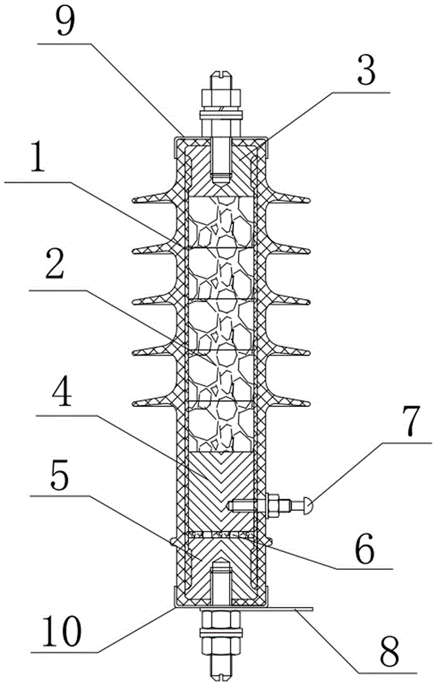
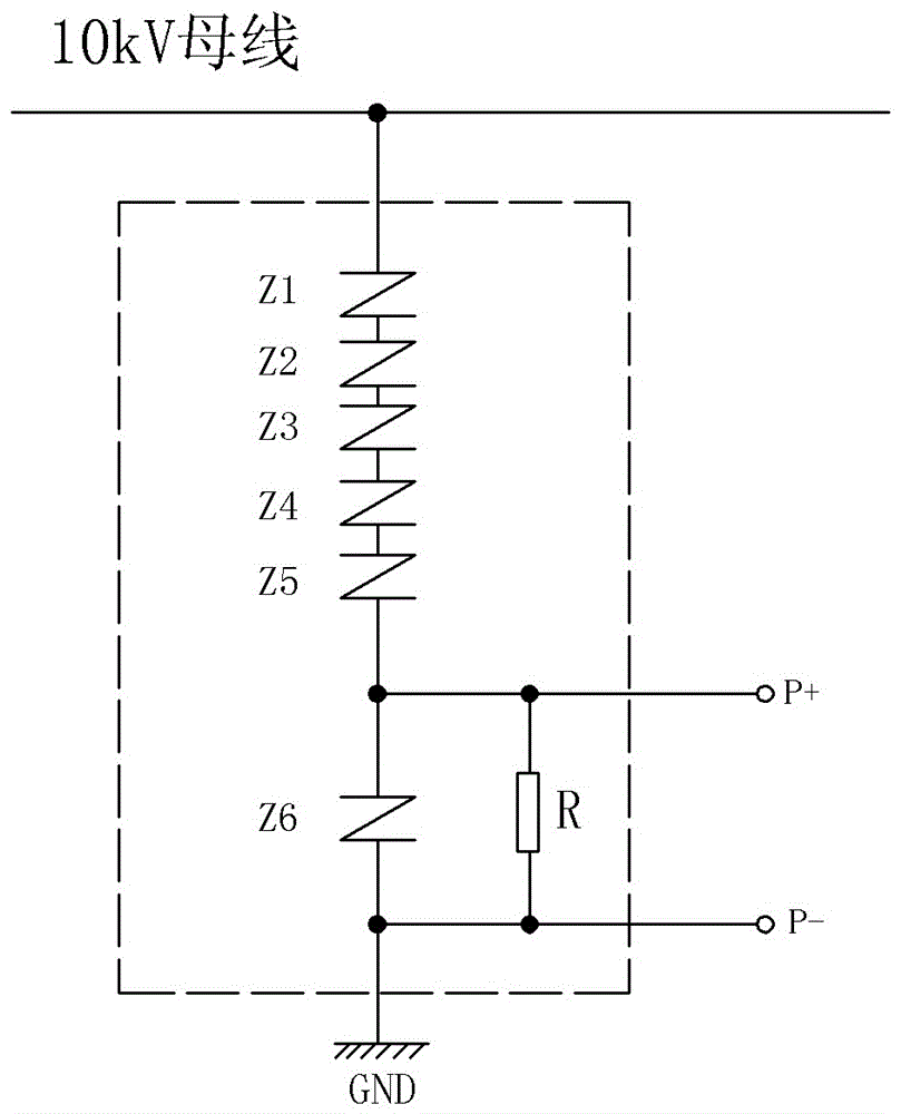
[0025] Embodiment 1: A lightning arrester with leakage current measurement function, which is used for the protection of 10kV lines, including an externally sealed umbrella case 1, and a core group composed of at least one metal oxide valve plate arranged inside the umbrella case 1 2. The first aluminum electrode 3 is provided on the upper part of the core group 2, and the leakage current measurement sensor is provided on the lower part; the leakage current measurement sensor includes the second aluminum electrode 4, the third aluminum electrode 5, and the second aluminum electrode 4 and the The resistance sheet 6 between the third aluminum electrodes 5, the second aluminum electrode 4 is arranged at the lower part of the core group 2, and the detection positive electrode 7 (P+) drawn out to the outside of the umbrella case 1 is arranged in the second aluminum electrode 4. The bottom of the three-aluminum electrode 5 leads to a detection negative electrode 8 (P-); the resistanc...

Embodiment 2

[0027] Embodiment 2: A lightning arrester with leakage current measurement function. The difference from Embodiment 1 is that the residual voltage value of the protection valve Z6 is 100V under the nominal current of 8 / 20us, and the resistance value of the sampling resistor R is 50Ω.

Embodiment 3

[0028] Embodiment 3: A kind of arrester with leakage current measurement function, this arrester is used for the protection of 110kV line, its structure is the same as embodiment 1, the difference is that the residual of the protection valve Z6 under the 8 / 20us nominal current The voltage value is 350V, and the resistance value of the sampling resistor R is 5Ω.


PUM


Abstract

The invention discloses a lightning arrester with the leak current measuring function. The lightning arrester aims to solve the technical problems that leak current detection in an existing lightning arrester is interfered by strong electromagnetism, signal extraction difficulty is large, and electrification monitoring can not be achieved easily. The lightning arrester comprises an umbrella cover with the sealed exterior, and a core set arranged in the umbrella cover. A first aluminum electrode is arranged on the upper portion of the core set, and a leak current measuring sensor is arranged on the lower portion of the core set; the leak current measuring sensor comprises a second aluminum electrode, a third aluminum electrode and a resistance disc, a detection positive electrode P+ led out to the exterior of the umbrella cover is arranged in the second aluminum electrode, and a detection negative electrode P- is led out from the bottom end of the third aluminum electrode; the resistance disc is formed by connecting a sampling resistor R and a protecting valve plate Z6 in parallel. The lightning arrester and the leak current measuring sensor are integrally arranged, the electrodes are led out and connected to a measuring instrument, and on the premise of not influencing the lightning protection effect of a lightning arrester body, electrification monitoring of leak currents of the lightning arrester is achieved.

Description

technical field [0001] The invention relates to the technical field of lightning arrester live monitoring, in particular to a lightning arrester with the function of measuring leakage current. Background technique [0002] The phenomenon of lightning in the atmosphere will bring harm to human survival and social activities, and the protection of lightning has always been a concern of people. For example, the arrester is an important protection component on the power line. When the power line is struck by lightning and overvoltage occurs at both ends of the arrester, the arrester changes from a high impedance state to a low impedance state, and quickly discharges the lightning strike current, thereby achieving protection for power equipment. When the arrester is in working state, the two ends continue to bear the working voltage, and the arrester presents high impedance at the rated working voltage. At this time, there will be a weak leakage current flowing through the arrest...

Claims


Application Information

Patent Timeline
Patent Type & Authority Patents(China)
IPC IPC(8): G01R31/02G01R19/00
Inventor 胡智宏王雯婷卢中宁
Owner 胡智宏
Learn More