
Power distribution grid fault positioning method with high precision and low cost

A technology of distribution network fault and location method, applied in high-precision, low-cost distribution network fault location, 3-10kV distribution network field, can solve the problem of large range, installation of a large number of detection devices, unfavorable fault repair and power restoration And other issues

Active Publication Date: 2015-01-21
ELECTRIC POWER RES INST OF GUANGDONG POWER GRID
View PDF5 Cites 14 Cited by
  • Summary
  • Abstract
  • Description
  • Claims
  • Application Information

AI Technical Summary

Problems solved by technology

However, the fault location realized by distribution network automation can only realize the section location. Considering the economic benefit and the optimal input and output, the general feeder line adopts the three-segment mode
However, for overhead lines in remote mountainous areas, it can reach more than 30 kilometers. Even if there are three sections, when a fault occurs, after fault isolation, the fault location range is at least 10 kilometers. The range is relatively large, which is not conducive to rapid fault repair and maintenance. call back request
[0004] The current distribution network fault location technology based on the principle of traveling waves has the following disadvantages: (1) The theoretical wave velocity is used to calculate the distance, and when there is a difference between the theoretical wave velocity and the actual wave velocity, the ranging accuracy will be affected; Install detection devices at the end of each line. Due to the huge number of distribution network ends, it is necessary to install a large number of detection devices, which is economical.

Method used


Image

  • Power distribution grid fault positioning method with high precision and low cost
  • Power distribution grid fault positioning method with high precision and low cost
  • Power distribution grid fault positioning method with high precision and low cost

Examples


Embodiment Construction

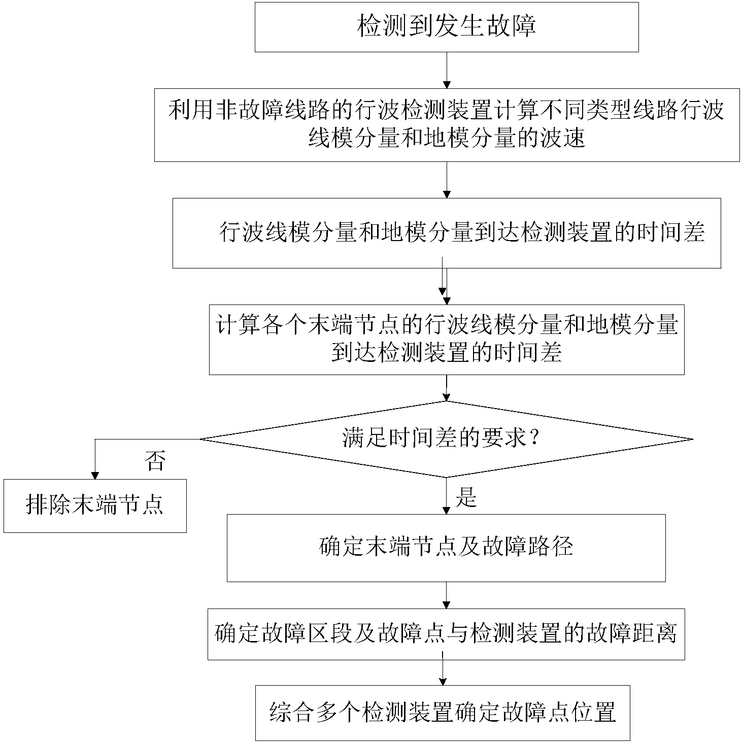
[0036] like figure 1 , the high-precision, low-cost distribution network fault location method of the present invention, comprises the following steps:

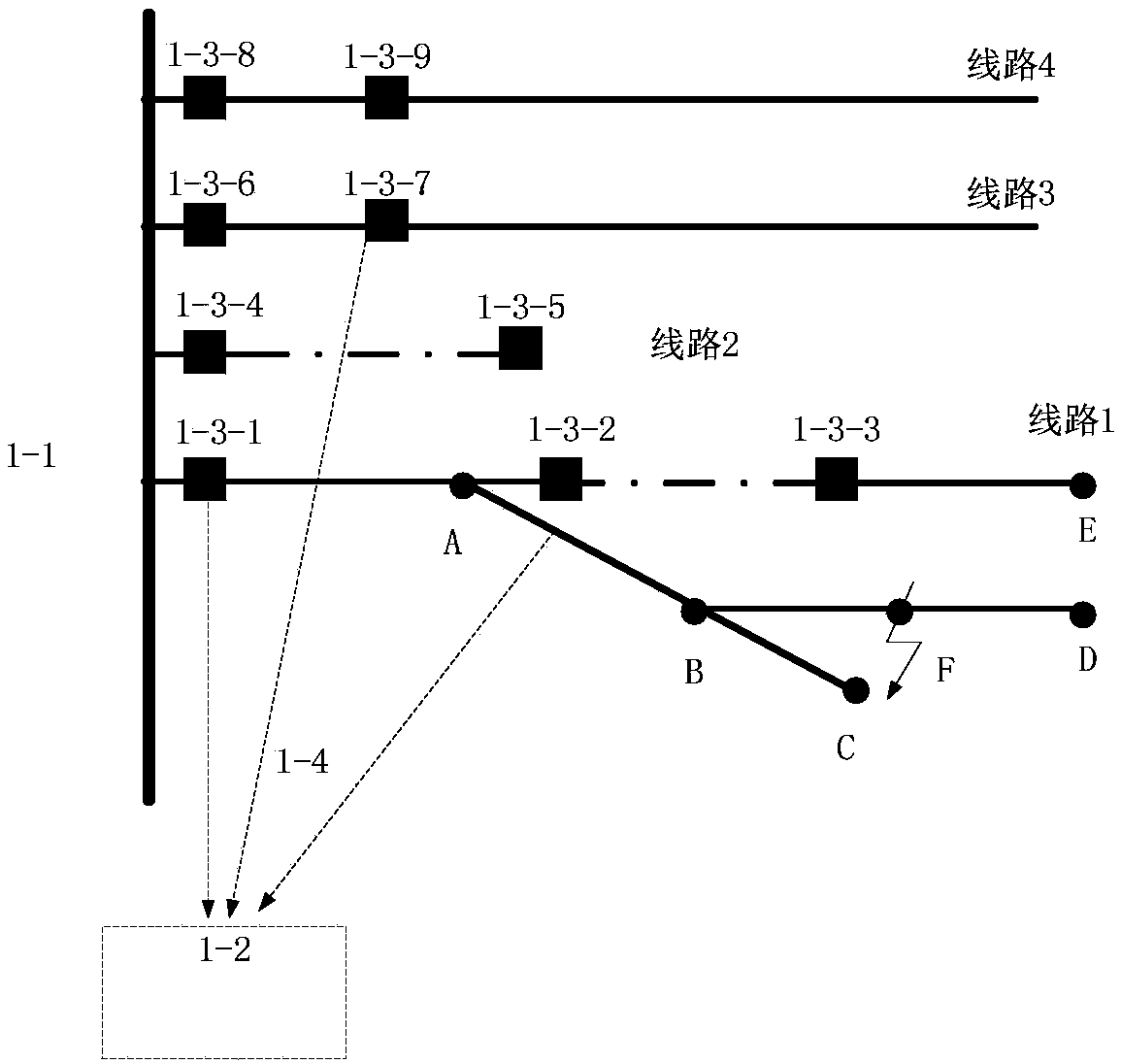
[0037] Step 1, for various types of transmission line sections with different traveling wave transmission speeds in the distribution network, including different types of sections of overhead transmission lines and cable transmission lines, select at least Two transmission line sections, and install traveling wave detection devices with GPS synchronous clocks at both ends of the selected transmission line sections; in order to reduce the amount of calculation and improve the speed of fault location in the distribution network, it is preferable to select 2~ Three transmission line sections are installed with traveling wave detection devices.

[0038] Step 2. When a fault occurs in the distribution network, use the step-1 line wave detection device to collect the data of the sudden change time of the line voltage and zero-sequ...


PUM


Abstract

The invention discloses a power distribution grid fault positioning method with high precision and low cost. According to the fault positioning method, a small amount of traveling wave detection devices with GPS time comparison functions are mounted at two ends of different overhead lines and cable lines of a power distribution grid; when the power distribution grid has faults, the wave speeds of traveling wave line mode component and floor mold component in different lines are calculated by using detection devices of a non-fault line, subsequently the distance of a fault point to one detection device is calculated according to the time difference of the traveling wave line mode component and the floor mold component reaching the detection device, and finally the position of the fault point is confirmed according to the ranging result of a plurality of detection devices. The power distribution grid fault positioning method can achieve accurate fault positioning, shortens the time for troubleshooting, improves the power supply reliability, is small in mounting equipment quantity and good in economy, and has very good practicability.

Description

technical field [0001] The invention relates to a high-precision and low-cost distribution network fault location method, which belongs to the technical field of electric power system automation and is suitable for 3-10kV distribution network. Background technique [0002] The research on precise fault location has always been one of the important topics in power system. At present, the relatively mature distance measuring devices applied to the power system are all aimed at the neutral point directly grounded system (110kV and above), and for the distribution network, due to its complex structure, the location of the fault point of the feeder has always been the research of accurate fault location. problem. [0003] Distribution network automation is an important means to reduce the time of fault outage, narrow the scope of fault outage, and improve the reliability of power supply. It usually includes fault location, fault isolation and restoration of power supply in non-f...

Claims


Application Information

Patent Timeline
IPC IPC(8): G01R31/08
CPCY04S10/52
Inventor 李传健陈炯聪郑文杰齐郑黄嘉健曾瑞江周克林陈辉张晓平宋旭东陈小军李志
Owner ELECTRIC POWER RES INST OF GUANGDONG POWER GRID
Learn More