Vertical polarization ceiling omni antenna

A vertically polarized, omnidirectional antenna technology, applied in the direction of the antenna, the structural connection of the antenna grounding switch, the structural form of the radiating element, etc., can solve the problems of high cost and difficult processing, and achieve low cost, reduced profile, and easy processing and production. Effect

Inactive Publication Date: 2015-01-21
JIANGSU EAST CENTURY NETWORK INFORMATION +1
View PDF12 Cites 17 Cited by
  • Summary
  • Abstract
  • Description
  • Claims
  • Application Information

AI Technical Summary

Problems solved by technology

Existing vertically polarized omnidirectional antennas have the defects of high processing difficulty and high cost

Method used


Image

  • Vertical polarization ceiling omni antenna
  • Vertical polarization ceiling omni antenna
  • Vertical polarization ceiling omni antenna

Examples


Embodiment Construction

[0028] Embodiments of the present invention are described in detail below, examples of which are shown in the drawings, wherein the same or similar reference numerals designate the same or similar elements or elements having the same or similar functions throughout. The embodiments described below by referring to the figures are exemplary and are intended to explain the present invention and should not be construed as limiting the present invention.

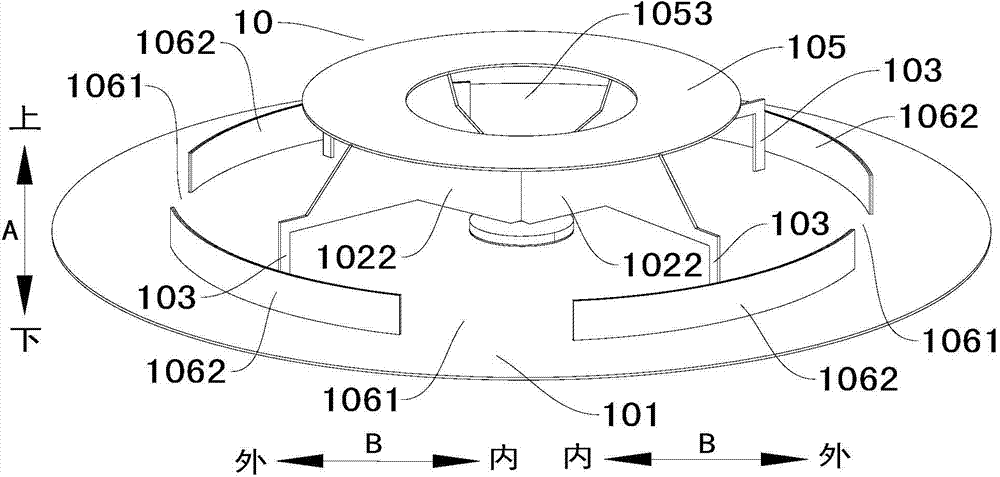
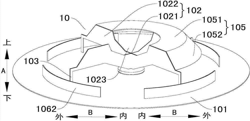
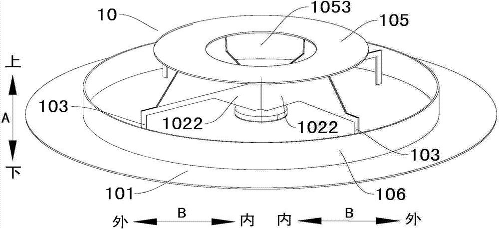
[0029] The present invention provides an antenna, and the antenna according to an embodiment of the present invention includes a vertically polarized ceiling omnidirectional antenna 10 and a horizontally polarized omnidirectional antenna 20 . The horizontally polarized omnidirectional antenna 20 is arranged above the vertically polarized ceiling omnidirectional antenna 10 .

[0030] first reference Figure 1-Figure 5 A vertically polarized ceiling omnidirectional antenna 10 according to an embodiment of the present invention is ...


PUM


Abstract

The invention discloses a vertical polarization ceiling omni antenna. The vertical polarization ceiling omni antenna comprises a reflecting plate, a short-circuit monopole, a plurality of short-circuit pins and a first coaxial cable. The short-circuit monopole comprises a center part and a plurality of radiation parts, the inner end of each radiation part is connected with the center part, each radiation part extends in the direction far away from the center part, and the short-circuit monopole is arranged above the reflecting plate. The short-circuit pins are correspondingly connected with the radiation parts in a one-to-one mode and connected with the reflecting plate. The first coaxial cable comprises a first outer conductor and a first inner conductor. The first outer conductor is connected with the reflecting plate, and the first inner conductor penetrates through the reflecting plate and is connected with the center part of the short-circuit monopole. The vertical polarization ceiling omni antenna has the advantages of being simple in structure, easy to machine and produce, low in cost and profile, small in size and the like.

Description

technical field [0001] The invention relates to a vertically polarized ceiling omnidirectional antenna. Background technique [0002] The existing vertically polarized omnidirectional antennas are all dish cone antennas and biconical antennas. The existing vertically polarized omnidirectional antenna has the defects of high processing difficulty and high cost. Contents of the invention [0003] The present invention aims to solve one of the technical problems in the related art at least to a certain extent. Therefore, an object of the present invention is to propose a vertically polarized ceiling-mounted omnidirectional antenna which has the advantages of simple structure, easy processing and production, low cost, low profile, and small volume. [0004] The vertically polarized ceiling omnidirectional antenna according to an embodiment of the present invention includes: a reflector; a short-circuit monopole, the short-circuit monopole includes a central part and a plural...

Claims


Application Information

Patent Timeline
Patent Type & Authority Applications(China)
IPC IPC(8): H01Q1/36H01Q19/10H01Q1/50
Inventor 漆一宏于伟
Owner JIANGSU EAST CENTURY NETWORK INFORMATION
Why Eureka
Try Eureka