
Double-axis solar tracker system device for solar power station

A system device and power station technology, applied in solar thermal power generation, solar heating system, solar thermal energy and other directions, can solve the problems of complex structure, inconvenient control method and low protection measures of the sun tracking system device, so as to improve the power generation efficiency of components , Accurate tracking position, good pulling effect

Inactive Publication Date: 2015-01-21
YANGZHOU XINGHUI ENERGY TECH
View PDF1 Cites 4 Cited by
  • Summary
  • Abstract
  • Description
  • Claims
  • Application Information

AI Technical Summary

Problems solved by technology

[0002] Nowadays, technologies that use solar energy to replace other energy sources are also continuously introduced. The existing solar tracking system device as described in the patent 200920249829.X mainly rotates through the supporting tube and the rotating tube to track The sun rotates from west to east, and the adjustment of the direct sunlight point is adjusted through the telescopic rod. This kind of solar tracking system has a complicated structure and poor tracking accuracy; the structure is resistant to wind load, the protection measures are not high, the maintenance frequency is high, and the control method is inconvenient

Method used


Image

  • Double-axis solar tracker system device for solar power station
  • Double-axis solar tracker system device for solar power station
  • Double-axis solar tracker system device for solar power station

Examples


Embodiment Construction

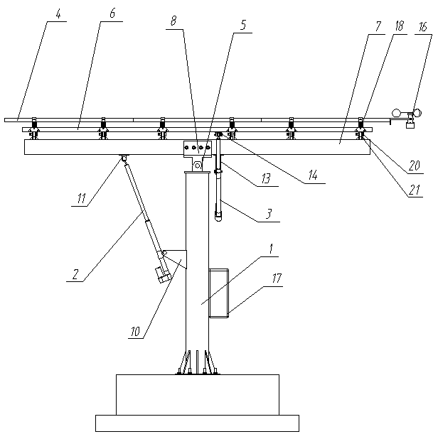
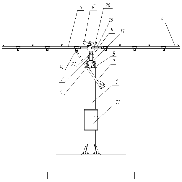
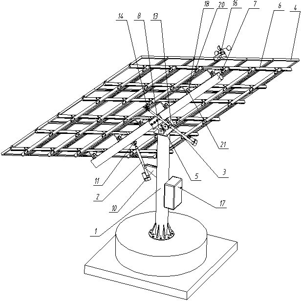
[0014] Such as figure 1 , 2 As shown in , 3, the dual-axis solar tracking system device of this solar power station includes a column 1, a first elevation angle push rod 2, a second elevation angle push rod 3, and a solar panel 4. The top of the column 1 is fixedly connected to the hinged seat 5, and the solar panel 4 A frame group 6 is arranged below, and a crossbeam tube 7 is hinged below the frame group 6, and the midpoint position of the crossbeam pipe 7 is fixedly connected to the hinged support 8, and the crossbeam tube 7 is hinged to the hinged seat 5 through the hinged support 8, the pin shaft 9; The first push rod support 10 is set on the vertical rod 1, the second push rod support 11 is set on the beam bar 7 on one side of the hinged support 5, and the first elevation angle push rod 2 is arranged on the first and second push rods. Between the bearings 10 and 11, the two ends of the first elevation angle push rod 2 are respectively hinged on the first and second push...


PUM


Abstract

The invention discloses a double-axis solar tracker system device for a solar power station and relates to the field of photovoltaic power generation, in particular to a tracking system mechanism of a photovoltaic power station. The double-axis solar tracker system device comprises a stand column, a first elevation push rod, a second elevation push rod and a solar panel, wherein a hinging base is fixedly connected to the top end of the stand column, a frame set is arranged below the solar panel, a beam tube is hinged to the lower side of the frame set, a hinging support is fixedly connected with the midpoint of the beam tube, and the beam tube is hinged to the hinging base through the hinging support and a pin shaft; a first push rod support is arranged on a stand rod, a second push rod support is arranged on the portion, on one side of the hinging support, of the beam tube, the first elevation push rod is arranged between the first push rod support and the second push rod support, a third push rod support is arranged on the portion, on the other side of the hinging support, of the beam tube, a fourth push rod support is arranged on a keel frame of the frame set below the solar panel and located on one side of the beam tube, and the second elevation push rod is arranged between the third push rod support and the fourth push rod support. According to the solar tracker system device, tracking direction is accurate, and therefore the power generating efficiency of a module is improved.

Description

technical field [0001] The invention relates to the field of photovoltaic power generation, in particular to a tracking system mechanism of a photovoltaic power station. Background technique [0002] Nowadays, technologies that use solar energy to replace other energy sources are also continuously introduced. The existing solar tracking system device as described in the patent 200920249829.X mainly rotates through the supporting tube and the rotating tube to track The sun rotates from west to east, and the adjustment of the direct sunlight point is adjusted through the telescopic rod. This kind of solar tracking system has a complicated structure and poor tracking accuracy; the structure is resistant to wind load, the protection measures are not high, the maintenance frequency is high, and the control method is inconvenient . Contents of the invention [0003] In order to overcome the above-mentioned defects, the present invention provides a dual-axis solar tracking s...

Claims


Application Information

Patent Timeline
IPC IPC(8): H02S20/32
CPCF24S30/455Y02E10/47Y02E10/50
Inventor 周正松
Owner YANGZHOU XINGHUI ENERGY TECH
Learn More