Spray arm for a dishwasher having two spray-arm parts

A technology of spray arm and dishwasher, applied in the field of spray arm, can solve the problem of high cost pressure, achieve the effect of improving strength and reducing consumption

Active Publication Date: 2015-01-21
ETIMEX TECHN COMPONENTS
View PDF8 Cites 2 Cited by
  • Summary
  • Abstract
  • Description
  • Claims
  • Application Information

AI Technical Summary

Problems solved by technology

Furthermore, the spray arm must be manufactured and assembled cost-effectively, since the cost pressures in the manufacture and assembly of such dishwashers are very high today in the field of domestic machines, but also in the field of industrial machines

Method used


Image

  • Spray arm for a dishwasher having two spray-arm parts
  • Spray arm for a dishwasher having two spray-arm parts
  • Spray arm for a dishwasher having two spray-arm parts

Examples


Embodiment Construction

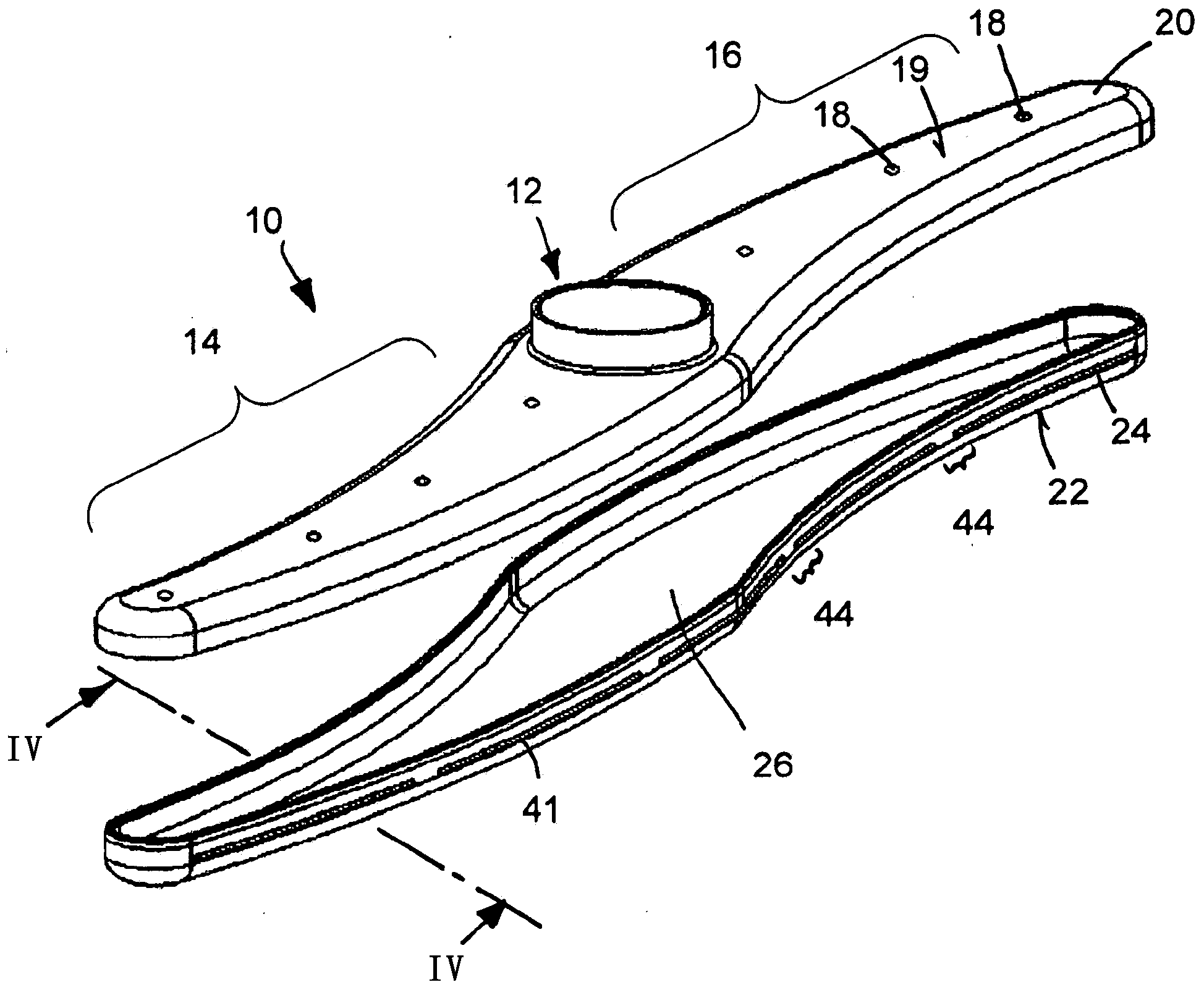
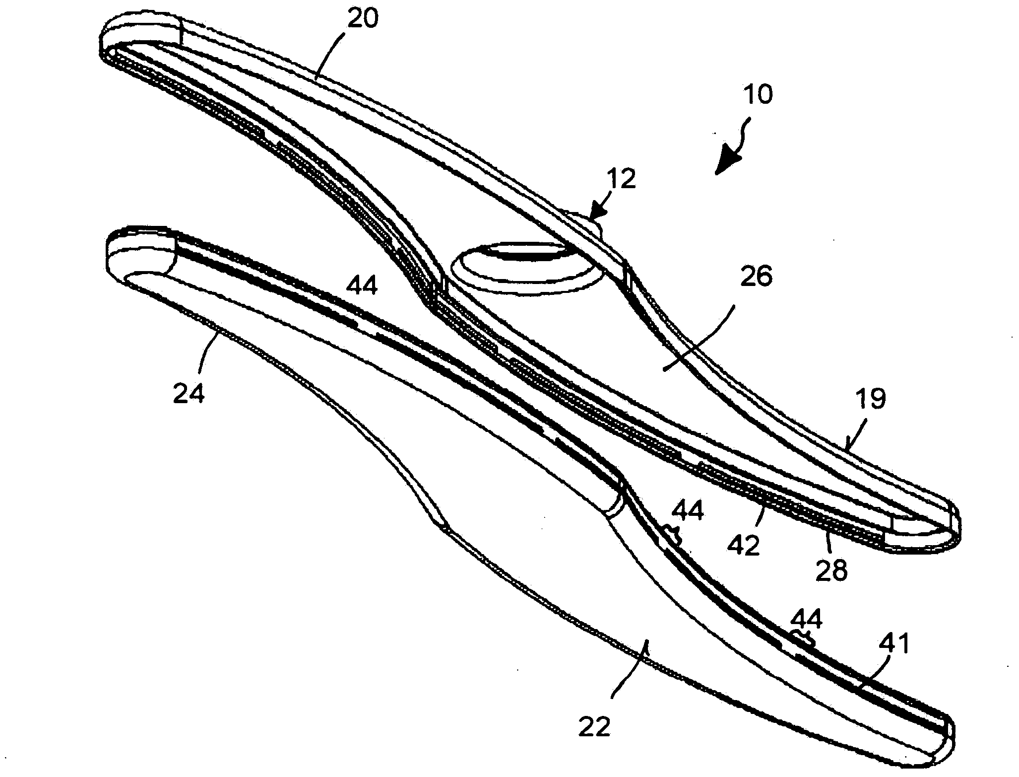
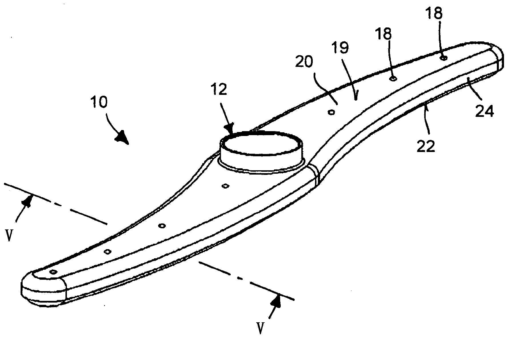
[0027] Shown in the figures is a spray arm 10 of a domestic dishwasher, not shown in detail, which has a vertical hollow-cylindrical hub section 12, two arm sections 14 and 16 along opposite sides. The direction extends horizontally from the hub section. In the installed state in the dishwasher, the spray arm 10 is supplied with water under pressure through the hub section 12, which is then sprayed out by nozzles 18, which are arranged in a distributed manner in the spray arm 10.

[0028] The nozzles 18 are distributed on the upper side 19 of the upper shell-shaped spray arm 20 and, if applicable, on the underside 22 of the likewise shell-shaped lower spray arm 24 . The spray arms 20 and 24 are here made of plastic by injection molding or, alternatively, by deep drawing of metal, in particular stainless steel, and in their shell shape each rest against each other in such a way that a cavity 26 is produced. .

[0029] The seam regions or connection regions between such mutua...


PUM


Abstract

In a spray arm for a dishwasher, comprising a first spray arm part and a second spray arm part, of which the first spray arm part comprises a groove which extends substantially along the circumference of the first spray arm part, said groove being formed by a first, inner groove wall and a second, outer groove wall, and of which the second spray arm part comprises a web wall which extends substantially along the circumference of the second spray arm part and engages with the groove, the web wall comprises a first latching element which, in order to establish a latching connection between the first and the second spray arm part, is designed to interact with a second latching element which is located on one of the groove walls.

Description

technical field [0001] The invention relates to a spray arm for a dishwasher, said spray arm having a first spray arm part and a second spray arm part, of which the first spray arm part The arm has a slot extending on the periphery of the first spray arm. Background technique [0002] In dishwashers, in particular used as domestic machines, rotating spray arms are provided for introducing and distributing wash water into the associated rinsing spaces. Spray arms are usually assembled from two spray arm parts which enclose a cavity. Wash water is introduced into the cavity, which is then sprayed out into the washing chamber of the dishwasher through nozzles, wherein the nozzles are arranged in at least one of the spray arms. [0003] In order to ensure proper functioning of such a spray arm, the cavity of the spray arm must be enclosed in a sealed manner by the two spray arm parts. Furthermore, the spray arm must be manufactured and assembled cost-effectively, since the co...

Claims


Application Information

Patent Timeline
Patent Type & Authority Applications(China)
IPC IPC(8): A47L15/23
CPCA47L15/4278A47L15/23
Inventor H·赫尔曼M·福格特
Owner ETIMEX TECHN COMPONENTS
Why Eureka
Try Eureka