Uninterrupted oxygen system

An oxygen supply system and oxygen supply technology, applied in the field of medical devices, can solve the problem that the oxygen supply system cannot achieve automatic and continuous oxygen supply.

Inactive Publication Date: 2015-01-28
北京中成航宇科技股份有限公司
View PDF6 Cites 11 Cited by
  • Summary
  • Abstract
  • Description
  • Claims
  • Application Information

AI Technical Summary

Problems solved by technology

[0006] Aiming at the problem that the current oxygen supply system cannot realize automatic and continuous oxygen supply, the embodiment of the present invention proposes an uninterrupted oxygen supply system

Method used


Image

  • Uninterrupted oxygen system

Examples


Embodiment Construction

[0038] A preferred embodiment of the present invention will be described below with reference to the accompanying drawings.

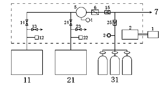
[0039] Attached below figure 1 The embodiments of the present invention are further described. The structure of the uninterrupted oxygen supply system of the embodiment of the present invention is as follows: figure 1 As shown, it includes: the main oxygen supply mechanism, the main oxygen supply mechanism includes at least two sets of oxygen supply units, such as figure 1 The illustrated embodiment is described by taking two sets of oxygen supply units as an example. Such as figure 1 As shown, it includes a first oxygen supply unit and a second oxygen supply unit, wherein the first oxygen supply unit includes a first oxygen generator unit 11, and the first oxygen generator unit 11 passes through the first oxygen generator unit 11 provided with a first gas generating electromagnetic valve 14. An oxygen supply branch is connected to the ox...


PUM


Abstract

The embodiment of the invention provides an uninterrupted oxygen system, comprising a main oxygen supply mechanism which at least includes a first oxygen supply unit and a second oxygen supply unit, wherein the first oxygen supply unit includes a first oxygen generation unit that is connected to an oxygen storage tank by a first oxygen supply branch with a first oxygen generation solenoid valve, the second oxygen supply unit includes a second oxygen generation unit that is connected to the oxygen storage tank by a second oxygen supply branch with a second oxygen generation solenoid valve, the oxygen storage tank is connected to an oxygen delivery pipe by a main oxygen supply pipe, and the main oxygen supply pipe is provided with a main oxygen supply pipe check valve.

Description

technical field [0001] The invention relates to the field of medical equipment, in particular to an uninterrupted oxygen supply system. Background technique [0002] In the medical field, oxygen supply equipment is indispensable, and its reliability is related to the life of patients. Oxygen in medical places must ensure continuous and sufficient oxygen supply at any time. [0003] The existing traditional oxygen supply mainly uses liquid oxygen and medical bottled gaseous oxygen as the gas source: [0004] In the existing liquid oxygen, the liquid oxygen in the storage tank is changed into a gaseous state through a vaporizer, and then supplied to wards, intensive care units and operating rooms through decompression. However, the production cost of liquid oxygen is high, a special vehicle is required for transportation, and the vaporizer and storage tank must be placed outdoors, the overall equipment occupies a relatively large space, and it needs to be operated by professi...

Claims


Application Information

Patent Timeline
Patent Type & Authority Applications(China)
IPC IPC(8): A61M16/00
Inventor 李建华李向东
Owner 北京中成航宇科技股份有限公司
Why Eureka
Try Eureka