Eureka AIR delivers breakthrough ideas for toughest innovation challenges, trusted by R&D personnel around the world.

Automatic pipe cutter

A pipe cutting machine, automatic technology, applied in the direction of pipe shearing device, shearing device, shearing machine accessories, etc., can solve the problems of increased manufacturing cost, and achieve the effect of reduced manufacturing cost and compact structure

Active Publication Date: 2015-01-28
WUXI AOTU AUTOMATION TECH CO LTD
View PDF6 Cites 13 Cited by
  • Summary
  • Abstract
  • Description
  • Claims
  • Application Information

AI Technical Summary

Problems solved by technology

Adopt hydraulic system and servo, increase manufacturing cost

Method used


Image

  • Automatic pipe cutter

Examples


Embodiment Construction

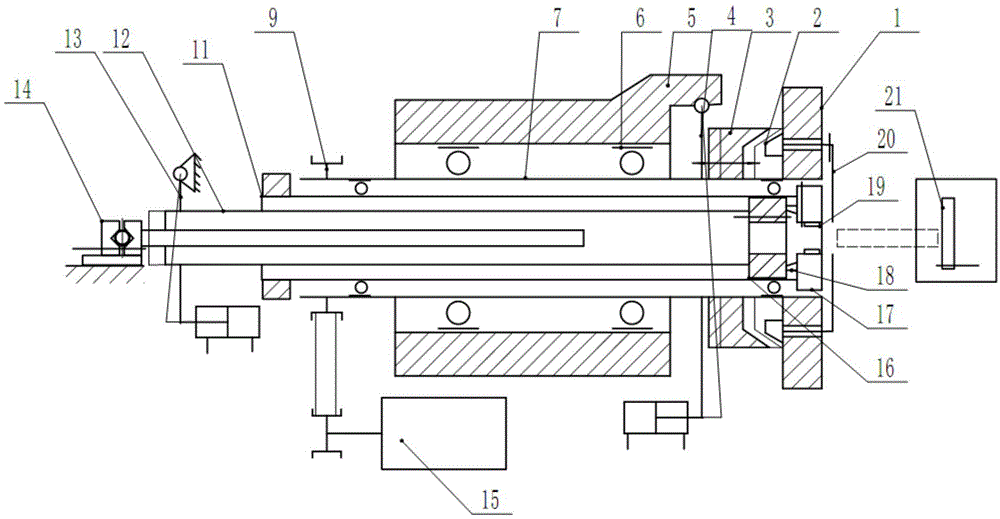
[0021] Such as figure 1 An automatic pipe cutting machine shown includes a feeding mechanism 14, a body 5, a hollow shaft sleeve 7, a chuck type clamping mechanism, a cutting mechanism and a limit backer 21; the feeding mechanism 14 is arranged at one end of the body 5, It is used to transport the pipe to be cut to the chuck-type clamping mechanism; the chuck-type clamping mechanism is located in the sleeve 7 and is used to clamp and lock the pipe to be cut; the sleeve 7 is set on the body 5 It is driven by a motor to rotate inside; the cutting mechanism is connected with the sleeve 7 and rotates with the sleeve 7 to cut the pipe to be cut; the limit backer 21 is set at the other end of the body 5 to control the length of the cut pipe ; One end of the chuck type clamping mechanism is provided with a clamping push rod 13; one end of the clamping push rod 13 is connected with a fixed pivot shaft, and the other end is connected with a cylinder; The radial displacement of the jaw...


PUM


Abstract

The invention discloses an automatic pipe cutter, which comprises a feeding mechanism, a body, a hollow shaft sleeve, a chuck type clamping mechanism, a cutting mechanism and a limiting backer. The automatic pipe cutter is characterized in that a clamping pushrod is arranged at one end of the chuck type clamping mechanism, wherein one end of the clamping pushrod is connected with a fixed pivoting shaft, and the other end of the clamping pushrod is connected with a cylinder; the axial displacement of the clamping pushrod is converted into the radial displacement of a clamping jaw of the chuck type clamping mechanism through a reversing mechanism to lock a pipe fitting to be cut. According to the automatic pipe cutter, a lever mechanism is used for magnifying pipe fitting locking pressure provided by the cylinder, and meanwhile, thrust is magnified according to a lever principle to drive a direction changing sleeve to move forwards to overcome the radial force during the rotation of the shaft sleeve and the cutting force of a cutting tool; a head is compact in structure, so that the manufacturing cost is greatly lowered; in addition, the clamping direction is the same as the cutting direction, so that the cut pipe fitting is ensured to directly fall.

Description

technical field [0001] The invention belongs to pipe cutting equipment, in particular to an automatic round pipe cutting machine. Background technique [0002] Existing pipe cutting machines usually use steel pipes to rotate, and the cutter is only used for feeding motion. However, due to the long length of steel pipe material, the vibration and noise generated by its rotation are very large, it is difficult to ensure the cutting accuracy, and the cutter is also easily damaged. Another type of pipe cutting machine does not rotate the steel pipe, the cutter rotates and feeds, and can cut long steel pipes, but its feeding movement is manual, which makes the feeding uneven and it is difficult to ensure the cutting quality. [0003] The reverse turning machine tool of the prior art adopts high-cost hydraulic propulsion and servo system to realize that the workpiece does not rotate and the tool rotates. Adopt servo and hydraulic system. Power is supplied to the servo motor thr...

Claims


Application Information

Patent Timeline
Patent Type & Authority Applications(China)
IPC IPC(8): B23D21/00B23D33/04
Inventor 朱马锋郭俊逸
Owner WUXI AOTU AUTOMATION TECH CO LTD
Why Eureka
Eureka Blog
Learn More