Silicone fluidized bed reactor with vibrating baffle plates

A silicon fluidized bed and baffle technology, applied in chemical instruments and methods, chemical/physical processes, etc., can solve the problems of time-consuming and labor-intensive, irregular cleaning, easy accumulation on baffles, etc. Time and labor costs, the effect of avoiding accumulation

Active Publication Date: 2019-03-29
HUAIYIN INSTITUTE OF TECHNOLOGY +1
View PDF20 Cites 1 Cited by
  • Summary
  • Abstract
  • Description
  • Claims
  • Application Information

AI Technical Summary

Problems solved by technology

Usually, the height of the silicon powder is between 5-10 meters, and the diameter of the reactor is 3 meters or more. If a baffle plate with a solid structure is used except for the tube hole, the reaction time between the silicon powder and methyl chloride gas will become longer. long, but solid silicon powder is

Method used


Image

  • Silicone fluidized bed reactor with vibrating baffle plates
  • Silicone fluidized bed reactor with vibrating baffle plates
  • Silicone fluidized bed reactor with vibrating baffle plates

Examples


Embodiment 1

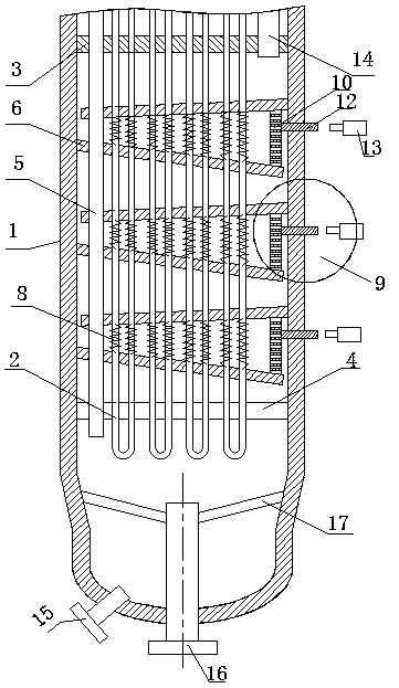
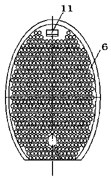
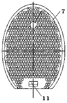
[0029] Such as Figure 1-7 Shown, a kind of organosilicon fluidized-bed reactor with vibrating baffle plate comprises cylinder body 1, heat exchange tube 2 and silicon powder feed pipe 5 in cylinder body 1, and in said cylinder body 1 The upper and lower ends are respectively fixedly connected to the solid fixed tube sheet 3 and the hollowed-out fixed tube sheet 4, and the heat exchange tube 2 and the silicon powder feeding tube 5 are fixedly connected to the solid fixed tube sheet 3 and the hollowed-out fixed tube sheet 4, There are five groups of baffle devices in the cylinder 1, the baffle devices include baffle a6 and baffle b7, and the heat exchange tube 2 and the silicon powder feed pipe 5 pass through the baffle a6 and the baffle b7 respectively. The baffle b7, the baffle a6 and the baffle b7 are arranged in opposite directions, and the area formed by the two is large at one end and small at the other end. The angle α between them is 35°, the baffle a6 and the baffle b...

Embodiment 2

[0034] Such as Figure 8 As shown, compared with Example 1, the further improvement of Example 2 is the top baffle a6 and the solid type Elastic parts 8 are also provided between the fixed tube sheets 3 and between the bottom baffle b7 of the bottom set of baffle devices and the hollowed-out fixed tube sheet 4. The advantage of this solution is to increase the baffle a6 and fold The vibration between the flow plates b7 has a better vibration effect and better avoids the accumulation of silicon powder.


PUM


Abstract

The invention discloses a silicone fluidized bed reactor with vibrating baffle plates. The silicone fluidized bed reactor comprises a cylindrical shell, a heat exchange tube in the cylindrical shell and a silicon powder feeding tube, at least one baffle device is arranged in the cylindrical shell, the baffle device comprises a baffle plate a and a baffle plate b, the oblique directions of the baffle plate a and the baffle plate b are opposite to each other, an area formed by the two baffle plates has one large end and one small end, and an elastic member is arranged between the baffle plate aand the baffle plate b. The structure of the reactor allows most of generated silicone gas to flow in the fluidized bed reactor in a zigzag direction. Compared with conventional reactors achieving I-shaped flow, the reactor in the invention has the advantages of long reaction time, sufficiency in the reaction of a chloromethane gas and silicon powder, significant reduction of the required height,rapid reduction of the content of the silicon powder under the layer barrier of the baffle plates, ensuring of the purity of the product silicone gas, and avoiding of deposition of the silicon powderthrough driving the baffle plates to vibrate by a driving device.

Description

technical field [0001] The invention relates to an organic silicon fluidized bed reactor, in particular to an organic silicon fluidized bed reactor with a vibrating baffle. Background technique [0002] One of the key equipment for organosilicon production is the synthesis reactor. At present, the organosilicon reactor mainly adopts a reactor between a fluidized bed and a fixed bed, which is customarily called a fluidized bed reactor in the industry. Because silicon powder is solid, it is difficult to feed silicon powder continuously. Usually, silicon powder is added to the reactor at one time, and methyl chloride gas is continuously fed from the bottom of the reactor. It is a semi-continuous and semi-batch reactor. The fluidized bed is a gas-solid phase reaction, so the baffles in the fluidized bed are the key factors to improve the performance of the reactor. [0003] The baffles in the existing fluidized bed reactor mainly have two structures at present, one is a solid c...

Claims


Application Information

Patent Timeline
IPC IPC(8): B01J8/40B01J8/00
CPCB01J8/008B01J8/40B01J2208/00132B01J2208/00548B01J2208/00929
Inventor 李伯奎冯清付黄梓庭王在良齐正王武谦
Owner HUAIYIN INSTITUTE OF TECHNOLOGY
Why Eureka
Try Eureka