Stator blade machining method of aeroengine compressor without mounting plate

An aero-engine technology without a mounting plate, which is applied in the direction of machines/engines, liquid fuel engines, mechanical equipment, etc., can solve the problems of low processing efficiency, low pass rate of blade profile, complex process, etc., and achieve high pass rate , Guaranteed contour and surface quality, and simple processing flow

Active Publication Date: 2015-01-28
AECC AVIATION POWER CO LTD
View PDF7 Cites 28 Cited by
  • Summary
  • Abstract
  • Description
  • Claims
  • Application Information

AI Technical Summary

Problems solved by technology

This method needs to process the airfoil profile, the process is complicated, the processing efficiency is low, and the pass rate of the blade profile i

Method used


Image

  • Stator blade machining method of aeroengine compressor without mounting plate
  • Stator blade machining method of aeroengine compressor without mounting plate
  • Stator blade machining method of aeroengine compressor without mounting plate

Examples


Embodiment Construction

[0018] The present invention will be described in detail below in conjunction with the accompanying drawings.

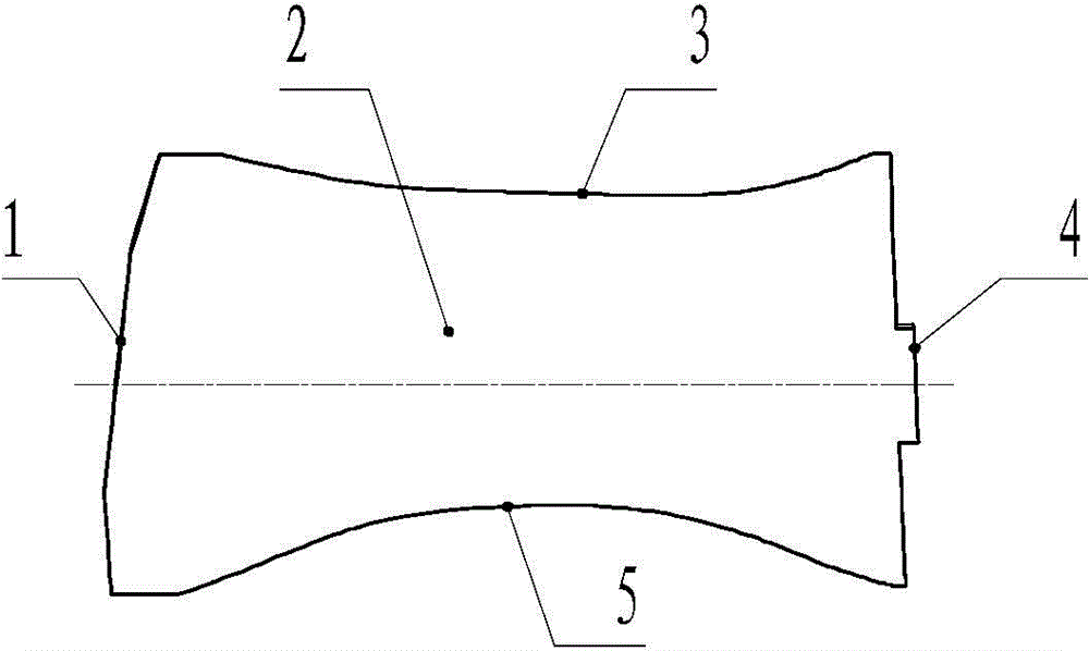
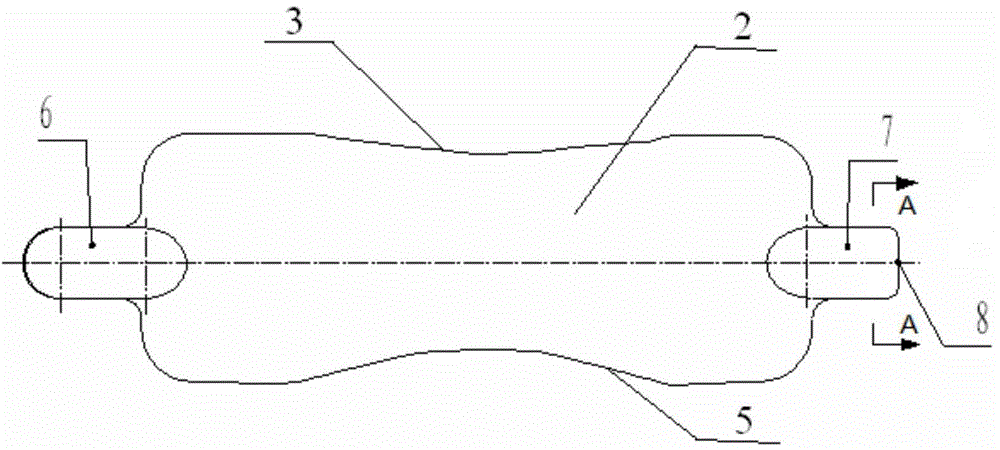
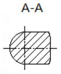
[0019] The blank of the aeroengine stator blade without mounting plate of the present invention is a precision forging, and the structure of the blank can be found in figure 2 and image 3 , the blank includes an airfoil 2, an exhaust edge 3 located on one side of the airfoil 2, an air intake edge 5 located on the other side of the airfoil 2, a first process boss 6 located at one end of the airfoil 2, and an The second process boss 7 at one end, where the airfoil 2 includes the blade tip 1 and the blade root 4, the blade tip 1 is connected to the first process boss 6, the blade root 4 is connected to the second process boss 7, and the blade body 2 has no margin , the intake side 5 and the exhaust side 3 have a machining allowance of 2 mm to 3 mm, and the end face 8 of the boss of the second process is the axial reference of the blade, and the processing steps are a...


PUM


Abstract

Disclosed is a stator blade machining method of aeroengine compressor with a mounting plate. The stator blade machining method includes adopting a stator blade blank without a mounting plate of a finish forge workpiece, positioning, clamping and machining an air inlet side and an exhaust side on a numerical-control milling machine by a first technical boss, a second technical boss, the end face of the second technical boss and a basin side of a blade body; polishing the air inlet side and the exhaust side, and ensuring that the size and the shape of the air inlet side and the exhaust side conform to the design requirements; positioning, clamping and machining a blade tip and a blade root on a numerical wire-cut machine by the basin side of the blade, the first technical boss, the second technical boss and the end face of the second technical boss, and removing the first technical boss and the second technical boss; finishing the blade tip and the blade root by clamps and removing wire-cut remelting layers on the blade tip and the blade root. By adopting the finish-forging blank, profile tolerance and surface quality of the molded profile of the blade are guaranteed, and the machined blade conforms to the design requirement and is high in yield. The stator blade machining method is simple in machining process, machining efficiency is effectively improved and machining period is shortened.

Description

technical field [0001] The invention belongs to the processing technology of aero-engine compressor blades, and relates to an improvement of a processing method for aero-engine compressor stator blades without mounting plates, in particular to a processing method for aero-engine compressor stator blades without mounting plates. Background technique [0002] For a certain type of engine compressor, a stator blade structure without a mounting plate, see figure 1 , the blade is composed of blade tip 1, blade body 2, exhaust edge 3, blade root 4 and intake edge 5. The blade tip 1 is composed of three sections of curved surfaces, the blade root 4 has steps, and the inlet edge 5 and the exhaust edge 3 are changing profiles. At present, the main methods of processing stator blades without mounting plates are as follows: 1) Using die forging blanks or sheets, first CNC milling the airfoil profile, then polishing the airfoil profile, and finally cutting off the blade tip and blade r...

Claims


Application Information

Patent Timeline
IPC IPC(8): B23P15/02
CPCB23P15/02F04D29/403
Inventor 冯全全马辉赵赟张新冬雷海峰秦仁章
Owner AECC AVIATION POWER CO LTD
Why Eureka
Try Eureka