Vacuum carrier

A vacuum and carrier technology, applied in the field of tooling and fixtures, can solve problems such as dead spots in product surface processing, small processing space for processing equipment, and affect assembly. The effect of compression deformation

Active Publication Date: 2017-01-11
昆山冠品优精密机械有限公司
View PDF7 Cites 0 Cited by
  • Summary
  • Abstract
  • Description
  • Claims
  • Application Information

AI Technical Summary

Problems solved by technology

[0002] With the rapid development of electronics, the surface processing of shell parts of electronic products is becoming more and more refined, the processing requirements are getting higher and higher, and the overall shell is getting thinner and thinner. Using traditional tooling to clamp and fix it on the processing equipment will cause The shell is deformed by force, which affects its subsequent assembly, and the clamping method will inevitably require two opposite surfaces to be clamped, which will cause dead spots on the surface of the product, and it is necessary to replace the clamping position before processing, resulting in the cumulative error of multiple positioning. There are also studs with internal threads or external threads arranged inside the casing, which are fixed on the processing equipment by bolts, and the studs are milled off after the processing is completed. This method causes complicated processing technology, takes time, and is easy The surface of the product is damaged during the subsequent milling process. Since the product needs to be processed with high precision, the processing space of the processing equipment is small, and there is no space for vacuum generation equipment. Therefore, the conventional vacuum adsorption method cannot be realized. How to realize the fixed positioning of the product without causing other Deformation under force and easy fixation have become an insurmountable technical problem in the processing of high-precision electronic product shells

Method used


Image

  • Vacuum carrier
  • Vacuum carrier
  • Vacuum carrier

Examples


Embodiment

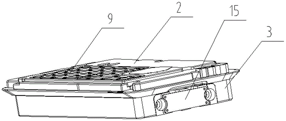
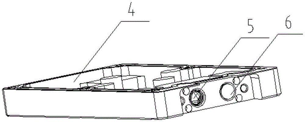
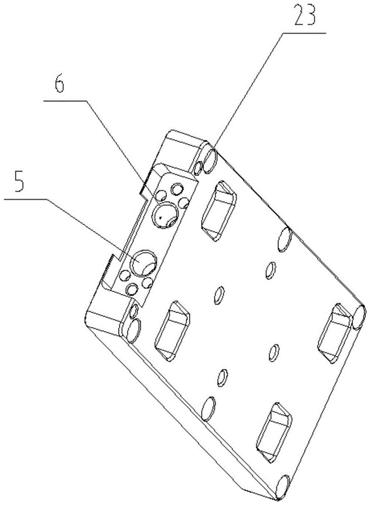
[0026] Embodiment: A vacuum carrier includes a carrier body 1. The carrier body 1 includes a top cover 2 and a main board 3. The top cover 2 can be disassembled and sealed to cover one side of the main board 3. A gap is formed between the top cover 2 and the main board 3. Sealed vacuum holding cavity 4, a vacuum loading port 5 and a vacuum releasing port 6 are respectively formed on the side wall of the vacuum holding cavity 4, and a vacuum charging port 5 is provided with a hole only for gas to flow out of the vacuum holding cavity 4 One-way valve 7, a sealing plug 8 capable of sealing the vacuum release port 6 is provided in the vacuum release port 6, the side of the top cover 2 facing away from the main board 3 is the outer side, the side facing the main board 3 is the inner side, and the top cover 2 is outside A number of concave cavities 9 matching the suction products are formed on the surface, a ring of sealing strips is provided on the edge of the concave cavities 9, an...


PUM


Abstract

The invention discloses a vacuum loading device. The vacuum loading device is characterized in that a loading device body comprises a top and a main board; a top cover can detachably cover one side of the main board by a sealing manner; a closed vacuum maintaining cavity is formed between the top cover and the main board; a vacuum loading port and a vacuum releasing port are respectively formed in the sidewall of the vacuum maintaining cavity; an one-way valve through while the air flows from the vacuum maintaining cavity is arranged in the vacuum loading port; a sealing plug for sealing the vacuum releasing port is arranged in the vacuum releasing port; the side of the top cover, back to the main board is the outer side, and the side of the top cover, toward the main board is the inner side; a plurality of inwards concave cavities which are matched with an actuation product are formed in the outer side surface of the top cover; a sealing strip is arranged like a loop on the side edges of the inwards concave cavity; air holes which are communicated with the vacuum maintaining cavity are arranged in the bottom surfaces of all the inwards concave cavities. According to the vacuum loading device, the loading device body enables fixed positioning of the product without any compressing force, and thus the product is avoided being pressed and deformed; in addition, a processing device is not provided with a vacuum generation device, so that the normal processing of high-precision and small-size processing devices is realized.

Description

technical field [0001] The invention relates to a tooling fixture, in particular to a vacuum carrier suitable for high-precision product processing. Background technique [0002] With the rapid development of electronics, the surface processing of shell parts of electronic products is becoming more and more refined, the processing requirements are getting higher and higher, and the overall shell is getting thinner and thinner. Using traditional tooling to clamp and fix it on the processing equipment will cause The shell is deformed by force, which affects its subsequent assembly, and the clamping method will inevitably require two opposite surfaces to be clamped, which will cause dead spots on the surface of the product, and it is necessary to replace the clamping position before processing, resulting in the cumulative error of multiple positioning. There are also studs with internal threads or external threads arranged inside the casing, which are fixed on the processing eq...

Claims


Application Information

Patent Timeline
Patent Type & Authority Patents(China)
IPC IPC(8): B23Q3/06
CPCB23Q3/088
Inventor 宇金龙
Owner 昆山冠品优精密机械有限公司
Why Eureka
Try Eureka