Vibrating burnisher

A finishing machine and vibrating shaft technology, which is applied to surface polishing machine tools, grinding/polishing equipment, machine tools suitable for grinding the edge of workpieces, etc. It can solve the problems of affecting the amplitude of the container, high maintenance costs, and heavy vibration motors. , to save equipment cost, facilitate maintenance and improve service life

Inactive Publication Date: 2015-01-28
杨芳丽
View PDF6 Cites 2 Cited by
  • Summary
  • Abstract
  • Description
  • Claims
  • Application Information

AI Technical Summary

Problems solved by technology

But the vibration source of existing vibrating finishing machine is vibrating motor, adopts vibrating motor to have the following problems: the first, the purchase price of vibrating motor is more expensive, and maintenance cost is higher, thereby has improved the cost of vibrating finishing machine, and Maintenance costs; Second, the vibration motor is installed at the bottom of the container, so it takes a lot of time to maintain the vibration motor, which affects production
Third, because the vibrating motor is heavy, installing it at the bottom of the container not only affects the amplitude of the container, but also increases the number and specifications of the springs between the container and the base, further increasing the cost of the vibrating finishing machine

Method used


Image

  • Vibrating burnisher

Examples


Embodiment Construction

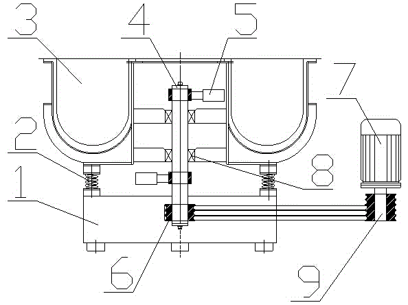
[0010] Embodiments of the present invention: the structure of the vibration finishing machine is as figure 1 As shown, during production, a base 1 is first welded with angle iron and thin steel plate, a spring 2 is installed on the base 1, and the other end of the spring 2 is correspondingly connected to the spring fixing point of the container 3; The bearing 8 is installed, the inner ring of the bearing 8 cooperates with the vibrating shaft 4, and two eccentric blocks 5 are connected to the vibrating shaft 4, and the two eccentric blocks 5 are respectively located on the symmetrical sides of the bearing 8, and at the same time, the bottom end of the vibrating shaft 4 is also Belt pulley 6 is installed, and motor 7 is set outside vibration finishing machine base 1, and belt pulley 9 is installed on the output shaft of motor 7, and belt pulley 6 is connected with the belt pulley 9 on the output shaft of motor 7 by belt.

[0011] When in use, the motor 7 arranged outside the bas...


PUM


Abstract

The invention discloses a vibrating burnisher. The vibrating burnisher comprises a base, wherein springs and a container are arranged on the base; a vibrating shaft is arranged on the container; an eccentric block and a belt wheel are connected to the vibrating shaft; the belt wheel is connected with a motor through a belt. Through mounting the vibrating shaft with the eccentric block and the belt wheel on the container of the vibrating burnisher and connecting the belt wheel on the vibrating shaft with the output shaft of the motor through the belt, the common motor can be used for driving the vibrating burnisher to work; the output shaft of the motor is connected with the vibrating shaft connected onto the container by a flexible connection means of the belt, the vibration of the vibrating shaft along with the container is not affected; a bearing is arranged at the connecting part of the container and the vibrating shaft, so that the service life of the vibrating shaft can be prolonged, and the rotating speed of the vibrating shaft can be improved; the motor is arranged outside the base, so that the motor can be conveniently maintained, and one motor can drive multiple vibrating burnishers with such structure to work; the equipment cost can be further saved.

Description

[0001] technical field [0002] The invention relates to a polishing device, in particular to a vibration polishing machine. Background technique [0003] When the existing vibrating finishing machine is working, the vibrating motor installed on the vibrating finishing machine container drives the container containing the workpiece and the grinding block to vibrate at a specific amplitude and frequency. The difference in the quality, shape and position of the grinding block forces the grinding block to collide, roll and micro-grind the workpiece, so as to realize the deburring, chamfering and surface finishing of the workpiece. But the vibration source of existing vibrating finishing machine is vibrating motor, adopts vibrating motor to have the following problems: the first, the purchase price of vibrating motor is more expensive, and maintenance cost is higher, thereby has improved the cost of vibrating finishing machine, and Maintenance costs; Second, the vibrating motor...

Claims


Application Information

Patent Timeline
Patent Type & Authority Applications(China)
IPC IPC(8): B24B31/067
CPCB24B31/067
Inventor 杨芳丽
Owner 杨芳丽
Why Eureka
Try Eureka