
Mechanical stirring slurry electrolyzer

A slurry electrolyzer and mechanical stirring technology, applied in the direction of electrolysis components, electrolysis process, cells, etc., can solve the problems of electrolysis work paralysis, high energy consumption, slow speed of mineral powder dissolution, etc., to reduce high energy consumption and equipment wear , The system structure is simple and reasonable, and the effect of improving the yield of electrolytic metal

Inactive Publication Date: 2016-08-17
赤壁神山兴农科技有限公司
View PDF5 Cites 0 Cited by
  • Summary
  • Abstract
  • Description
  • Claims
  • Application Information

AI Technical Summary

Problems solved by technology

[0005] Mineral powder will settle in the electrolytic tank. The biggest difficulty in the actual electrolysis process is the suspension of the ore pulp. If the ore pulp cannot achieve a good suspension, the acid produced by electrolysis cannot react well with the mineral powder and dissolve the mineral powder. The speed of the electrolysis slows down, and the concentration of metal ions in the electrolytic cell is also difficult to increase, so that the electrolysis cannot be carried out smoothly.
If electrolysis cannot be carried out smoothly, the acid produced by electrolysis will be less, and the speed of mineral powder dissolution will be slower, resulting in a vicious circle, which will eventually paralyze the electrolysis work
[0006] The most common means to achieve slurry suspension is stirring, but ordinary mechanical stirring can only make the slurry suspend better when the stirring paddle is small and stirring fast, but the energy consumption of such a stirring device will be very high during operation. High and large electrolyzers require multiple stirring devices to achieve the normal operation of electrolysis, and it is impossible to simultaneously sweep the bottom of the electrolyzer and continuously treat the non-suspendable mineral powder particles to make them suspend, so now Some technologies cannot meet the requirements of pulp electrolysis

Method used


Image

  • Mechanical stirring slurry electrolyzer
  • Mechanical stirring slurry electrolyzer

Examples


Embodiment Construction

[0020] Now in conjunction with accompanying drawing, the present invention is described in further detail.

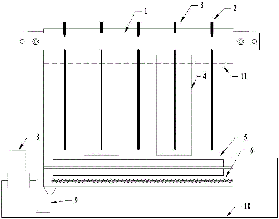
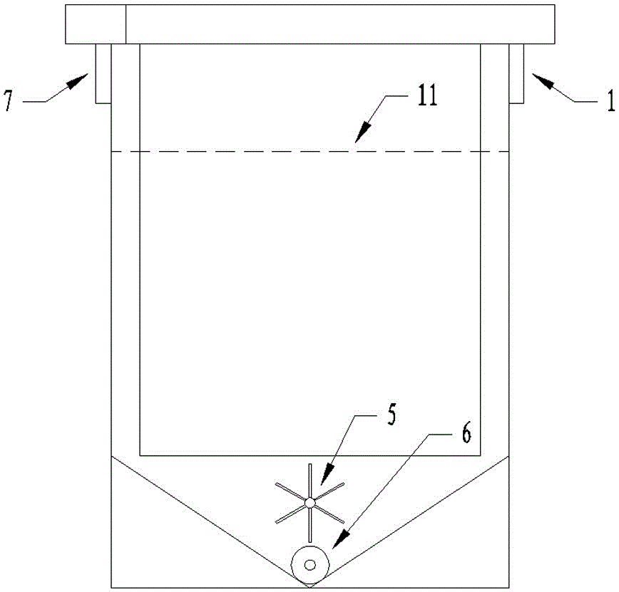
[0021] Such as figure 1 with figure 2 The mechanically agitated slurry electrolyzer shown includes positive copper strip 1, anode plate 2, negative copper strip 7, cathode plate 3 and electrolytic diaphragm 4, and the pole plates 2, 3 and positive and negative copper strips 1, 7 are all V-shaped. Overlapping; the middle and lower part of the electrolytic cell is provided with a horizontally arranged long-axis stirring paddle 5; the bottom of the electrolytic cell is provided with a horizontally arranged screw conveyor 6, and the delivery end of the screw conveyor 6 is provided with a cone bottom structure, and the cone bottom passes through The discharge pipe 9 is connected to the wet pulverizer 8, and the wet pulverizer 8 is connected to the electrolytic cell through the conveying pipe 10.

[0022] The mechanically stirred slurry electrolyzer is generally made of an...


PUM


Abstract

The invention discloses a mechanical agitation type ore pulp electrolytic cell. The mechanical agitation type ore pulp electrolytic cell comprises a positive electrode copper bar, an anode plate, a negative electrode copper bar, a cathode plate and an electrolytic diaphragm, wherein the anode plate and the cathode plate are in V-shaped connection with the positive electrode copper bar and the negative electrode copper bar in an overlapped mode; transversely-arranged long shaft agitator blades are arranged on the lower middle portion of the electrolytic cell; a transversely-arranged spiral conveyor is arranged at the bottom of the electrolytic cell, a conical bottom structure is arranged at the conveying end of the spiral conveyor, a conical bottom is connected with a wet pulverizer through a discharge tube, and the wet pulverizer is connected with the electrolytic cell through a conveying tube. The mechanical agitation type ore pulp electrolytic cell is simple and reasonable in structure, the anode plate and the cathode plate are in V-shaped connection with the positive electrode copper bar and the negative electrode copper bar in the overlapped mode so that the distance between the anode plate and the cathode plate can be accurately determined conveniently, and reliable contact is guaranteed; the low-speed long-blade large-area sweeping of the agitation device is more suitable for maintaining suspension of ore pulp for a long time with low energy consumption; the pulverizer is combined with the spiral conveyor so that the ore pulp can be reliably suspended and electrolyzed, increase of the electrolytic metal production rate can be promoted due to secondary pulverization of coarse particles, and the mechanical agitation type ore pulp electrolytic cell is particularly suitable for large-scale production and wide in prospect.

Description

technical field [0001] The invention relates to a mechanically stirred pulp electrolyzer, which is especially suitable for electrolytic pulp. Background technique [0002] The electrolytic cell is the key equipment supporting the electrolysis industry of lead, zinc, manganese, aluminum and other metals. However, most of the existing electrolytic cells can only electrolyze the solution, but not the electrolytic slurry. That is, the electrolytic solution must be prepared before electrolysis. . [0003] The preparation of mineral powder into electrolyte requires multiple steps such as compounding, dissolution, pressure filtration and impurity removal. The cost of many steps is high, and there is still a certain loss in the preparation process. If the mineral powder can be directly made into slurry in the electrolytic cell Electrolysis can greatly simplify the process, reduce intermediate links, save costs and increase product yield. [0004] The essence of slurry electrolysis...

Claims


Application Information

Patent Timeline
Patent Type & Authority Patents(China)
IPC IPC(8): C25C7/00
Inventor 银永忠颜文斌高峰左凯
Owner 赤壁神山兴农科技有限公司
Learn More