Supercharge Your Innovation With Domain-Expert AI Agents!

Conical concrete pile tip, tubular pile provided with pile tip and production method of tubular pile

A technology for concrete piles and a manufacturing method, applied in the directions of manufacturing tools, sheet pile walls, reinforcing forming, etc., can solve the problems of uneven welding quality of picket piles, small stress-bearing area of ​​the cone tip, affecting the quality of pile foundations, etc. Insufficient bearing capacity of the pile tip, good integrity, and the effect of eliminating the welding connection process

Inactive Publication Date: 2015-01-28
大连力宏建筑材料有限公司
View PDF5 Cites 5 Cited by
  • Summary
  • Abstract
  • Description
  • Claims
  • Application Information

AI Technical Summary

Problems solved by technology

The quality of picket piles and welding used in existing projects is uneven, which affects the quality of pile foundations, especially in geological conditions with hard interlayers and dense sand layers, it will be difficult to sink piles and there will be many rotten piles
[0004] The existing concrete pile tip is mainly conical, and the tip of the cone is prone to inclination when it is inserted into the ground during the construction process, and the force-bearing area of ​​the tip of the cone is small, especially when the bearing layer is a rock surface, it is too small to bear The area is easy to cause the pile tip to be broken, which directly affects the quality of the project

Method used


Image

  • Conical concrete pile tip, tubular pile provided with pile tip and production method of tubular pile
  • Conical concrete pile tip, tubular pile provided with pile tip and production method of tubular pile
  • Conical concrete pile tip, tubular pile provided with pile tip and production method of tubular pile

Examples


Embodiment 1

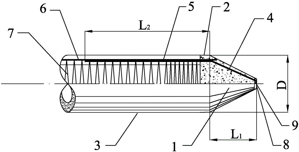
[0033] Such as figure 1 As shown, a cone-shaped concrete pile point, the pile point is a cone-shaped pile point formed by pouring concrete from the pile point main body 1, wherein the pile point body 1 includes a positioning plate 8 arranged at the end of the small head of the cone , the positioning plate 8 adopts a steel plate, and a hole 9 is arranged in the middle of the positioning plate 8, and a plurality of pile tip side ribs 4 are uniformly welded on the positioning plate 8 according to the standard reinforcement quantity of the pipe pile to form the pile tip main body 1 The end of the pile tip side rib 4 is fixed on the positioning plate 8, that is, it is fixed around the hole 9, and the pile tip is not fixed when the pile tip is assembled by screw tightening. Offset phenomenon occurs; the tail of the pile tip side rib 4 is provided with a bending part 5 for pouring to form the transition section 2 between the pile tip and the pile body, and the bending part 5 is conne...

Embodiment 2

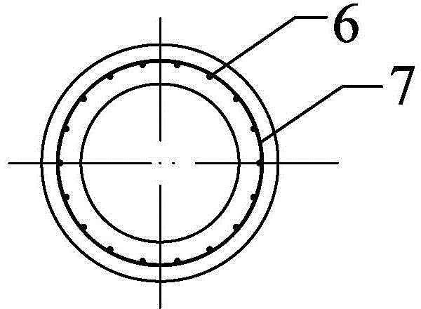
[0036] Such as figure 1 , 2 As shown, a pipe pile with the above-mentioned cone-shaped concrete pile point, the pipe pile is formed by the prestressed main reinforcement 6 of the pile body body 3 first and the bending part of the pile point side rib reinforcement 4 of the pile point 5 is formed by pouring concrete after being fixed, wherein the pile main body 3 includes prestressed main reinforcement 6 matching the number of side ribs 4 of the pile point and braided and wound around the outer periphery of the prestressed main reinforcement 6 with As for the stirrup 7 constituting the reinforcement cage of the pipe pile, the bending part 5 of the rib bar 4 on the side of the pile point and the main prestressed bar 6 are fixed by iron wires.

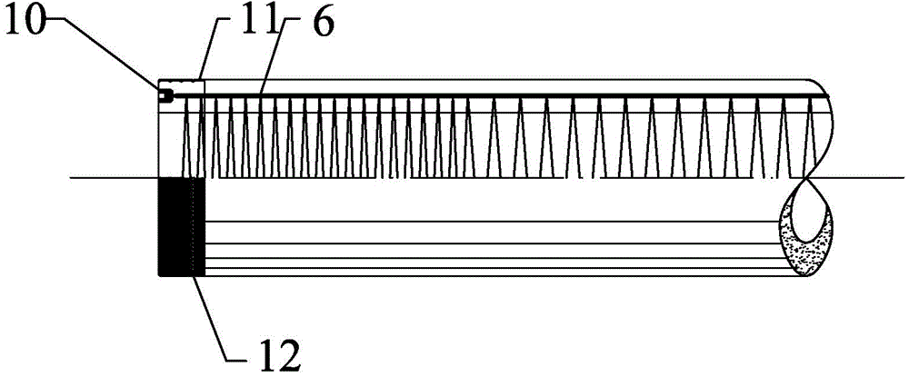
[0037] Such as image 3 , 4 As shown, the tail end of the pipe pile is provided with a plurality of anchor sleeves 10 for fixing the prestressed main reinforcement 6, and a pile hoop 11 is fixed outside the tail end of the pipe pile. A...

Embodiment 3

[0040] A method of manufacturing the above pipe pile, comprising the steps of:

[0041]Step 1: Make the main body 1 of the pile point, bend the steel bars into the side ribs 4 of the pile point, and then evenly weld and fix them on the positioning plate 8 to form the frustum-shaped skeleton of the pile point main body 1, and keep the side ribs of the pile point The height of the ribs 4 is consistent, and the ribs 4 on the side of the pile tip also include a bending part 5 for forming the transition section 2 between the pile tip and the pile body;

[0042] Step 2: Pouring the pile tip, place the pile tip body 1 in the pile tip mold, and there are evenly a number of reserved main reinforcement holes in the pile tip mold, and clean the mold opening and the inner wall of the mold and apply an appropriate amount of demoulding Put the iron shoe cover into the pile tip mold, cover the mold cover and screw the pile tip rod and check whether the iron shoe cover is perpendicular to the...


PUM


Abstract

The invention discloses a conical concrete pile tip, which is characterized in that the pile tip is a conical pile tip formed by pouring a pile tip body through concrete, wherein the pile tip body comprises a locating plate arranged at the end part of a small head of a circular table, a hole is arranged in the middle of the locating plate, a plurality of side ribs of the pile tip are uniformly fixed on the locating plate to form a conical skeleton of the pile tip body, and the ends of the side ribs of the pile tip are fixed on the locating plate; a bending part used for pouring to form a connection transition section of the pile tip and a pile body is arranged at the tail part of each of side ribs of the pile tip, and each bending part is parallel to a central shaft of the pile tip. The invention further discloses a tubular pile provided with the pile tip and a production method of the tubular pile. The tubular pile provided with the pile tip has the advantages of convenience for transportation, strong penetrating power, good integrity, simple production process of the tubular pile and low cost; the concrete pile tip replaces a steel pile tip, so that the concrete pile tips are integrally connected during molding of the tubular pile, and thus a welded connection process for the steel pile tip is omitted and a large amount of steel resources are saved; the tubular pile is suitable for requirements on different engineering and geological conditions.

Description

technical field [0001] The invention relates to a prestressed high-strength concrete pipe pile used in the building material industry, in particular to a conical concrete pile point, a pipe pile with the pile point and a manufacturing method of the pipe pile. Background technique [0002] Since the prestressed concrete pipe pile was introduced from Japan to my country in the early 1990s, it has been rapidly promoted in the north and south of the river because of its advantages of reliable quality, low engineering cost, and fast construction speed. Prestressed concrete pipe pile foundation has become the main pile type of civil construction pile foundation in economically developed areas. [0003] At present, the traditional domestic steel pile tip is separated from the pile body, and is connected by welding during construction. At present, the country or industry has no technical specifications for the connection between the steel pile tip and the pile body, and the bearing ...

Claims


Application Information

Patent Timeline
IPC IPC(8): E02D5/72E02D5/58
CPCE02D5/72B28B11/245B28B21/16B28B21/62B28B21/66E02D5/58E02D2200/16E02D2300/002
Inventor 袁雪峰王宏力
Owner 大连力宏建筑材料有限公司
Features
  • R&D
  • Intellectual Property
  • Life Sciences
  • Materials
  • Tech Scout
  • Unparalleled Data Quality
  • Higher Quality Content
  • 60% Fewer Hallucinations
Learn More