Multi-blade trench cutting machine
A slotting machine and blade technology, applied in construction, building structure and other directions, can solve the problems of loose saw blades, waste of energy, increased workload, etc., and achieve the effect of avoiding idling, improving efficiency and reducing workload.
- Summary
- Abstract
- Description
- Claims
- Application Information
AI Technical Summary
Problems solved by technology
Method used
Image

Examples
Embodiment 1
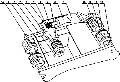
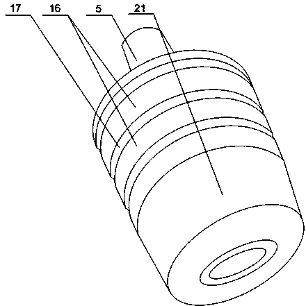
[0023] Such as Figure 1 to Figure 4 As shown, this embodiment includes a housing 1 and a motor 2 installed inside the housing 1. A movable cavity 9 with an open bottom is opened in the middle of the housing 1, and a bevel gear is fixedly arranged on the output end of the motor 2. A4, a rotating shaft 5 is installed in the housing 1, and a saw blade clamping head 7 is installed on one end of the rotating shaft 5, and the saw blade clamping head 7 is placed in the movable cavity 9, and the other end of the rotating shaft 5 is installed with a cone The bevel gear B6 matched with the gear A4; the saw blade clamping head 7 includes a nut 21, a plurality of clamping blocks 16 and movable blocks 19 that are slidably arranged on the rotating shaft 5, and between two adjacent clamping blocks 16 A gap 17 is left, and an annular groove 20 is oppositely arranged on two adjacent clamping blocks 16. The movable block 19 can move freely in the annular groove 20, and the movable block 19 is ...
Embodiment 2
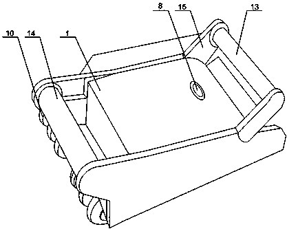
[0026] Such as figure 1 and figure 2As shown, in this embodiment, on the basis of Embodiment 1, a rear armrest 14 is installed at one end of the housing 1, and two supporting plates 15 arranged in parallel are installed on the other end of the housing 1, and the two supporting plates 15 is connected by front armrest 13. When in use, the operator holds the movable handle and the fixed handle respectively to cooperate with a plurality of rollers 10 to push the movement of the housing 1, wherein the movable handle is installed between two support plates 15, when the movable handle is pressed down, the saw blade is cutting the wall Larger vibrations will be generated when the operator is in the body. Through the buffering effect of the two armrests, the impact of vibration on the hands of the operator is greatly reduced, further reducing the workload of the operator.
[0027] It also includes a fixed cylinder 3 installed on the housing 1 , and the rotating shaft 5 is rotatably ...
Embodiment 3
[0029] Such as figure 1 and figure 2 As shown, this embodiment is based on Embodiment 1, and the movable cavity 9 is provided with a through hole 8 communicating with the outside. Since the saw blade rotates at a high speed when cutting, there will be continuous friction with the wall or the ground, which will generate a large amount of heat. The closed bottom end of the movable cavity 9 is provided with a through hole 8 communicating with the outside world. Depending on the structure of the body or the ground, the through hole 8 can be connected with a water pipe or a vacuum cleaner. When the temperature of the saw blade increases or the amount of dust in the movable cavity 9 increases, cooling water is injected or drawn out of the movable cavity 9. The accumulation of dust can not only ensure the normal use of the present invention, but also avoid a large amount of dust from polluting the operating environment.
PUM
 Abstract
Description
Claims
Application Information
 - R&D
- Intellectual Property
- Life Sciences
- Materials
- Tech Scout
- Unparalleled Data Quality
- Higher Quality Content
- 60% Fewer Hallucinations
Browse by: Latest US Patents, China's latest patents, Technical Efficacy Thesaurus, Application Domain, Technology Topic, Popular Technical Reports.
© 2025 PatSnap. All rights reserved.Legal|Privacy policy|Modern Slavery Act Transparency Statement|Sitemap|About US| Contact US: help@patsnap.com