Compact composite material power transmission line tower

A technology of power transmission lines and composite materials, applied in the field of power transmission and distribution engineering, can solve the problems of high probability of gap discharge accidents, small insulation margin of insulator strings, and high probability of discharge accidents, so as to reduce the width of corridors, ensure safe operation, and save projects. effect of investment

Active Publication Date: 2015-01-28
GANSU ELECTRIC POWER DESIGN INST
View PDF6 Cites 5 Cited by
  • Summary
  • Abstract
  • Description
  • Claims
  • Application Information

AI Technical Summary

Problems solved by technology

The structure of a conventional compact transmission line is as follows: Figure 5 Shown: Since the three-phase wires are in the same tower window, the tower window is large, consumes more steel, uses more insulators, and the project investment is high. In order to avoid the tower windo...

Method used


Image

  • Compact composite material power transmission line tower
  • Compact composite material power transmission line tower
  • Compact composite material power transmission line tower

Examples


Embodiment 1

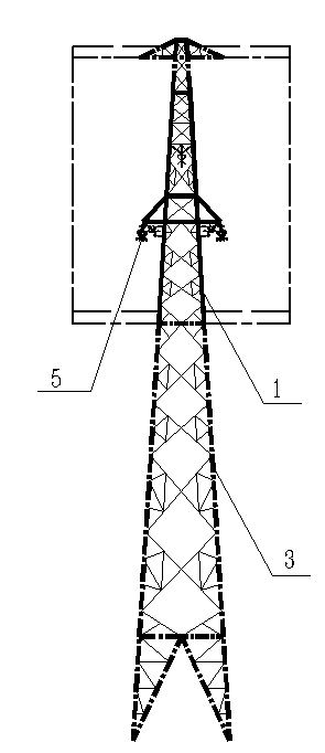
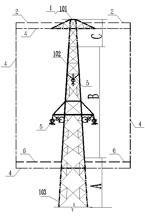
[0017] Example 1, such as figure 1 and figure 2 Shown: a compact transmission line tower made of composite materials, including a steel tower body 3, a tower head 1, and a wire hanging fitting 5; the tower head 1 includes an upper tower head 101, a middle tower head 102, a lower tower head 103, an The tower head 101 and the lower tower head 103 are steel tower heads, the middle tower head 102 is a composite material tower head, the lower end of the upper tower head 101 is fixedly connected with the upper end of the middle tower head 102, and the lower end of the middle tower head 102 is fixed with the upper end of the lower tower head 103 Connection, wire hanging fittings 5 ​​are installed in the tower head 102 in the middle section. In order to show the three-section tower head of the present invention clearly, the C section shown in the figure is the upper section head 101 , the B section is the middle section head 102 , and the A section is the lower section head 103 . ...

Embodiment 2

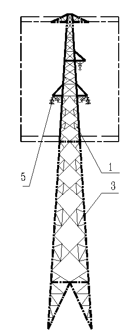
[0021] Example 2, such as image 3 and Figure 4 As shown: in the composite material compact transmission line tower provided in this embodiment, the wire-hanging fittings 5 ​​installed on the tower head 102 in the middle section are arranged in an upward shape; On the left and right sides of the body, another wire fitting 5 is installed on the right side of the middle tower head 102 upper tower body; certainly another wire hanging fitting 5 can also be installed on the middle tower head 102 upper tower body on the left side. The three-phase conductors of this scheme are arranged in non-equilateral triangles, and the charge balance of the three-phase conductors is slightly worse than that of the regular triangular composite material compact scheme. Others are the same as in Example 1.

[0022] The equilateral triangular composite material compact transmission line pole tower implementation scheme provided in Example 1 and the up-shaped composite material compact transmissio...


PUM


Abstract

The invention belongs to the transmission and distribution engineering field and relates to overhead power transmission line towers, particularly to a compact composite material power transmission line tower. The compact composite material power transmission line tower comprises a steel tower body, a tower head and a line hanging hardware fitting; the tower head comprises an upper section of tower head, a middle section of tower head and a lower section of tower head; the upper section of tower head and the lower section of tower head are steel tower heads; the middle section of tower head is a composite material tower head; the lower end of the upper section of tower head is fixedly connected with the upper end of the middle section of tower head; the lower end of the middle section of tower head is fixedly connected with the upper end of the lower section of tower head; the line hanging hardware fitting is arranged on the middle section of tower head; a metal crawling ladder which is arranged in a rectangular shape roughly is fixedly arranged between the upper section of tower head and the lower section of tower head. According to the compact composite material power transmission line tower, the structure is simple, the force is clear, and the engineering cost is low; the head portion of the steel power is formed by composite materials and accordingly a grounding component is not arranged among compact line three phases and the purposes of the improvement of the natural power and the reduction of the width of a corridor are implemented; a gas gap and the insulating strength can be increased and the safe operation can be ensured due to the composite materials; the compact composite material power transmission line tower can be applied to 330 kV, 500 kV and 750 kV circuits.

Description

technical field [0001] The invention belongs to the field of power transmission and distribution engineering, and relates to an overhead power transmission line tower, in particular to a composite material compact power transmission line tower. Background technique [0002] The definition of compact overhead transmission line is: through the optimized arrangement of the wires, the three-phase wires are placed in the same tower window, and there is no grounding component between the three-phase wires, so as to increase the natural transmission power, reduce the width of the corridor, and increase the width of the unit corridor. capacity of overhead transmission lines. The structure of a conventional compact transmission line is as follows: Figure 5 Shown: Since the three-phase wires are in the same tower window, the tower window is large, consumes more steel, uses more insulators, and the project investment is high. In addition, in order to avoid the tower window being too l...

Claims


Application Information

Patent Timeline
IPC IPC(8): E04H12/02
CPCE04H12/02
Inventor 杨光刘行奎杨立健蒋剑段辉顺贺建国安维忠李毓冯友生
Owner GANSU ELECTRIC POWER DESIGN INST
Why Eureka
Try Eureka