Power cable sheath and installation method of the sheath

A sheath and power technology, applied in building types, buildings, towers, etc., can solve problems such as corrosion of wire-pulling hardware, hidden dangers of safe operation, and difficulty in finding wire-pulling hardware, so as to achieve the effect of prolonging service life and good air permeability.

Active Publication Date: 2016-05-04
STATE GRID HEBEI RAOYANG COUNTY POWER SUPPLY
View PDF7 Cites 0 Cited by
  • Summary
  • Abstract
  • Description
  • Claims
  • Application Information

AI Technical Summary

Problems solved by technology

In daily work, it is often found that there is no serious corrosion of the hardware without the cable sheath after 10 or even 20 years of use, while the hardware with the cable sheath installed, the rainwater will flow down the cable and flow into the cable sheath However, its tightly closed structure makes it difficult for rainwater to flow out and form moisture, which corrodes the cable fittings for a long time
It is difficult to find that the wire fittings are corroded, which will bring hidden dangers to the safe operation in the future

Method used


Image

  • Power cable sheath and installation method of the sheath
  • Power cable sheath and installation method of the sheath
  • Power cable sheath and installation method of the sheath

Examples


Embodiment Construction

[0025] The power cable sheath proposed by the present invention will be further described below in conjunction with the accompanying drawings.

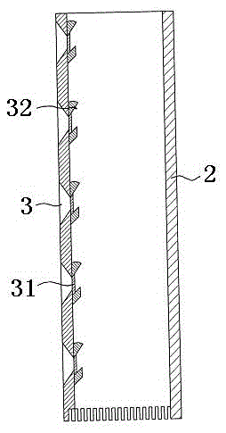
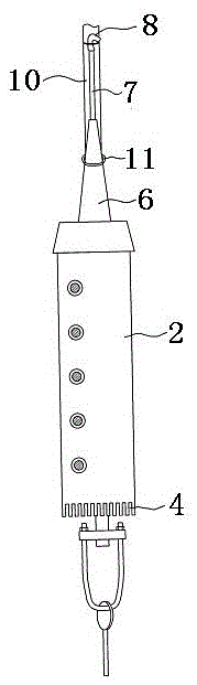
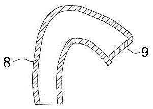
[0026] Such as figure 1 , figure 2 and image 3 Shown is the schematic diagram of the structure of the power cable sheath. The power cable sheath includes a sheath tube body 2 with an end cap 1 on the upper end, a plurality of vent holes 3 arranged in the axial direction are arranged on the sheath body 2, and There are a plurality of drainage grooves 4 arranged in the circumferential direction of the body, and a wire hole 5 is provided at the center of the end cover 1. On one side of the wire hole 5, a conical suction pipe 6 is provided, and an air guide pipe 7 is installed above the suction pipe 6. An elbow 8 is arranged at the upper end of the air duct 7 , and a first filter screen 9 is arranged at the end of the elbow 8 . Such as Figure 4 As shown, during installation, the vent hole 3 is positioned at the side of the backguy...


PUM


Abstract

The invention belongs to the technical field of bracing wire protective sleeves and discloses an electric power bracing wire protective sleeve and an installation method thereof. The electric power bracing wire protective sleeve is mainly characterized by comprising a protective sleeve pipe with the upper end provided with an end cover; a plurality of air holes which are arranged along the axial direction are formed in the protective sleeve body; the lower end of the protective sleeve body is provided with a plurality of drainage grooves which are arranged along the circumference of the protective sleeve body; a circular-truncated-cone-shaped air suction pipe is arranged on the end cover; an air guiding pie is installed above the air suction pipe; the upper end of the air guiding pipe is provided with a bending head; the end portion of the bending head is provided with a first filter screen. When the electric power bracing wire protective sleeve is installed, the air holes are in the lateral side of the bracing wire, the air guiding pipe is unbent along the bracing wire direction, the bending head is fixed on the bracing wire, the air suction pipe is in the circular truncated cone shape, a height difference exists between the upper end of the air guiding pipe and the lower end of the protective sleeve, the peripheral air pressure has a certain pressure difference, air enters the drainage grooves and the air holes and flows out from the bending head, water remains in hardware fittings and the bracing wire is blow-dry in time, the bracing line and the hardware fittings are avoided from longtime corrosion, and the gas permeability of the protective sleeve is good.

Description

technical field [0001] The invention belongs to the technical field of pull wire sheaths, and in particular relates to a power pull wire sheath and an installation method for the sheath. Background technique [0002] With the intensification of the transformation of distribution lines in recent years, the distribution lines and supporting facilities have been continuously improved. The number of installations of cable sheaths is increasing day by day, but the problems that follow are also becoming more prominent. In daily work, it is often found that there is no serious corrosion of the hardware without the cable sheath after 10 or even 20 years of use, while the hardware with the cable sheath installed, the rainwater will flow down the cable and flow into the cable sheath However, its tightly closed structure makes it difficult for rainwater to flow out and form moisture, which corrodes the cable fittings for a long time. It is difficult to find that the wire fittings are...

Claims


Application Information

Patent Timeline
Patent Type & Authority Patents(China)
IPC IPC(8): E04H12/20
CPCE04H12/20
Inventor 贾月发蒙苗王军伟
Owner STATE GRID HEBEI RAOYANG COUNTY POWER SUPPLY
Why Eureka
Try Eureka