Pneumatic sealing device

A pneumatic sealing and sealing lip technology, which is applied in the direction of engine sealing, fluid pressure actuating device, engine components, etc., can solve the problems of unfavorable reciprocating motion, easy damage of seals, poor sealing effect, etc., and achieve favorable reciprocating motion, Effect of reducing friction and improving fit

Inactive Publication Date: 2015-01-28
QINGDAO TKS SEALING IND
View PDF7 Cites 2 Cited by
  • Summary
  • Abstract
  • Description
  • Claims
  • Application Information

AI Technical Summary

Problems solved by technology

[0003] The invention provides a pneumatic sealing device to solve the problems of thin main sealing lip, low pressure bearing and short service life of the existing single-structure sealing ring, and overcome especially the poor sealing effect of pneumatic high pressure and fast movement, Seals are easily damaged, not conducive to reciprocating motion and easy to reverse lip and other defects, to meet the needs of actual sealing

Method used


Image

  • Pneumatic sealing device
  • Pneumatic sealing device

Examples


Embodiment 1

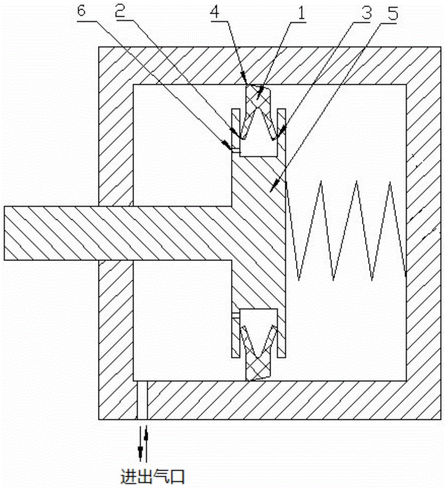
[0022] A pneumatic sealing device includes a rubber body 1, a piston body 5 and a cylinder; the piston body 5 is arranged in the cylinder; a groove is provided on the piston body 5, and the rubber body 1 is installed in the groove; the rubber body 1 A first sealing lip 2 and a second sealing lip 3 are provided, and the first sealing lip 2 and the second sealing lip 3 are in interference contact with the side wall of the groove of the piston body 5 .

Embodiment 2

[0024] A pneumatic sealing device, similar to Embodiment 1, the difference is that the rubber body 1 is also provided with a thickened third sealing lip 4; the third sealing lip 4 is in interference contact with the inner wall of the cylinder; the cylinder is provided with the left end of the cylinder cavity; the groove of the piston body 5 is provided with a number of small holes 6; the third sealing lip 4 is set as a rounded structure; the rubber body 1 is set as a "herringbone" structure; the first sealing lip 2 and the second sealing lip 3 are respectively The third sealing lip 4 is arranged at the top position of the "herringbone" shape structure of the rubber body 1 .

[0025] The rubber body 1 is installed in the groove of the piston body 5, the first sealing lip 2 and the second sealing lip 3 are in contact with the side wall of the groove of the piston body 5 and have a certain amount of interference, and the third sealing lip 4 is in contact with the cylinder The inn...

Embodiment 3

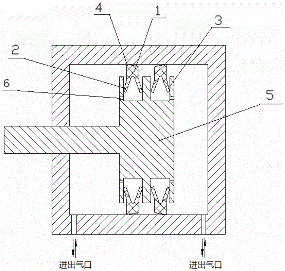
[0027] A pneumatic sealing device, which is similar to Embodiment 2, except that at least two grooves are evenly arranged on the piston body 5, and a rubber body 1 is respectively installed in each groove. Both sides of the cylinder are symmetrically provided with inlet and outlet ports.


PUM


Abstract

The invention relates to a pneumatic sealing device which comprises a rubber body, a piston body and an air cylinder, wherein the piston body is arranged in the air cylinder, a groove is formed in the piston body, and the rubber body is mounted in the groove; a first sealing lip, a second sealing lip and a third sealing lip are arranged on the rubber body, the first sealing lip and the second sealing lip are in interference contact with the side wall of the groove of the piston, and the third sealing lip is in interference contact with the wall of the air cylinder. The force situation of the sealing lips is improved by applying compressed air, so that the reliability, the fatigue resistance, the pressure resistance and the abrasion resistance of a sealing ring are improved. The pneumatic sealing device can solve the problems of thin main sealing lip, small bearing pressure and short service life of the current sealing ring with a single structure, overcomes the defects of poor sealing effect, easiness in damage of a sealing piece, bad reciprocating motion and easiness in lip reversing, and is especially suitable for the demand of pneumatic high-pressure and fast-moving sealing.

Description

technical field [0001] The invention belongs to the technical field of sealing and relates to a sealing device, in particular to a pneumatic sealing device. Background technique [0002] The traditional sealing structure mostly adopts the combination of ordinary rubber body and metal body, and most of them are a single sealing ring structure, which often has the problems of thin main sealing lip, low pressure and short service life, and the lip is stressed. The condition is not good, which leads to poor sealing effect, easy damage to the seal, unfavorable high pressure, fast reciprocating movement and easy back lip and other defects, which are difficult to meet the actual sealing needs. Therefore, a sealing device capable of solving the above-mentioned problems is needed to meet the actual sealing requirements. Contents of the invention [0003] The invention provides a pneumatic sealing device to solve the problems of thin main sealing lip, low pressure bearing and short...

Claims


Application Information

Patent Timeline
Patent Type & Authority Applications(China)
IPC IPC(8): F15B15/14F15B15/20F16J9/00
CPCF15B15/1447F16J15/3232
Inventor 蔡涌王东梅
Owner QINGDAO TKS SEALING IND
Why Eureka
Try Eureka