Manual-automatic integration type wireless-control intelligent electromagnetic valve
A wireless control, solenoid valve technology, applied in valve details, valve device, valve shell structure and other directions, can solve the problems of low safety factor, difficult control, high labor intensity, etc., to achieve easy control, reduce labor intensity, and reduce installation. The effect of cost of use
- Summary
- Abstract
- Description
- Claims
- Application Information
AI Technical Summary
Problems solved by technology
Method used
Image
Examples
Embodiment 1
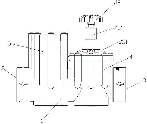
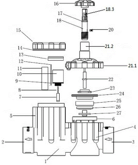
[0061] A manual and automatic wireless control intelligent solenoid valve, such as figure 1 As shown, it includes a valve body 1, a manual operation structure and an electromagnetic operation structure.
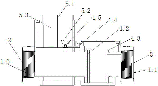
[0062] Such as image 3 As shown, the left and right sides of the bottom of the valve body 1 are respectively provided with a water outlet 2 and a water inlet 3, and the left and right sides of the top are respectively provided with a control chamber 5 and a main valve chamber 4, and the gap between the control chamber 5 and the main valve chamber 4 A valve body guide hole 1.4 is provided, and the water outlet 2 and the water inlet 3 are respectively provided with a water outlet external thread 1.6 and a water inlet external thread 1.1; the inside of the control chamber 5 is divided into sequentially connected battery installation slots 5.3, circuit boards The installation groove 5.1 and the coil installation seat 5.2, and the bottom of the coil installation seat 5.2 is prov...
Embodiment 2
[0072] This embodiment is basically the same as Embodiment 1, the difference between the two is:
[0073] The top of the above-mentioned manual rotary rod 18 is provided with a manual rotary handle 16;
[0074] The diaphragm fixing structure further includes a rubber pad 26 , and the first diaphragm fixing clip 23 , the diaphragm 24 , the second diaphragm fixing clip 25 and the rubber pad 26 pass through the bottom of the diaphragm guide rod 22 in sequence.
[0075]
Embodiment 3
[0077] This embodiment is basically the same as Embodiment 1, the difference between the two is:
[0078] Such as Figure 9As shown, the microelectronic circuit board 12 includes a microcontroller, a wireless transceiver module, a wireless communication module, a power management circuit module, a boost circuit module, a drive circuit module and an antenna;
[0079] The output end of the above-mentioned power management circuit module is electrically connected with the above-mentioned boosting circuit module, the driving circuit module and the electromagnetic coil 10 in turn, and its output end is also connected with the input end of the microcontroller, and its input end is connected with the battery box 11;
[0080] The input end and the output end of the above-mentioned microcontroller are respectively connected with the output end and the input end of the above-mentioned wireless transceiver module, and the wireless transceiver module is connected with the above-mentioned ...
PUM
 Abstract
Description
Claims
Application Information
 - R&D
- Intellectual Property
- Life Sciences
- Materials
- Tech Scout
- Unparalleled Data Quality
- Higher Quality Content
- 60% Fewer Hallucinations
Browse by: Latest US Patents, China's latest patents, Technical Efficacy Thesaurus, Application Domain, Technology Topic, Popular Technical Reports.
© 2025 PatSnap. All rights reserved.Legal|Privacy policy|Modern Slavery Act Transparency Statement|Sitemap|About US| Contact US: help@patsnap.com


