
Electromagnet for electromagnetic valve

An electromagnet and solenoid valve technology, applied in the field of solenoid valves, can solve problems such as affecting system stability and reducing system performance, and achieve the effects of ensuring stability, increasing damping effect, and alleviating impact force.

Active Publication Date: 2015-01-28
宁波市鄞州通力液压电器厂
View PDF12 Cites 1 Cited by
  • Summary
  • Abstract
  • Description
  • Claims
  • Application Information

AI Technical Summary

Problems solved by technology

Because the cross-section of the push rod of the electromagnet of the prior art is hexagonal, the oil flux of the oil passage formed between the push rod outer wall and the iron core inner wall is relatively large, and because the two axial oil passages on the armature directly It communicates with the inner cavity of the guide sleeve, and the oil flux is also very large. Therefore, the damping effect of the hydraulic oil on the push rod and the armature is very small, so the movement of the push rod and the armature will generate a large impact force, which will affect the operation of the entire system. stability, reducing system performance

Method used


Image

  • Electromagnet for electromagnetic valve
  • Electromagnet for electromagnetic valve
  • Electromagnet for electromagnetic valve

Examples


Embodiment Construction

[0021] The present invention will be further described below in conjunction with the accompanying drawings and specific embodiments.

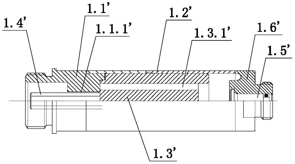
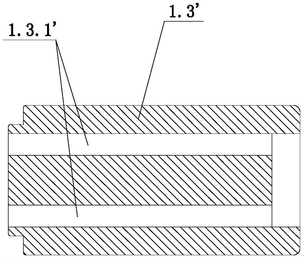
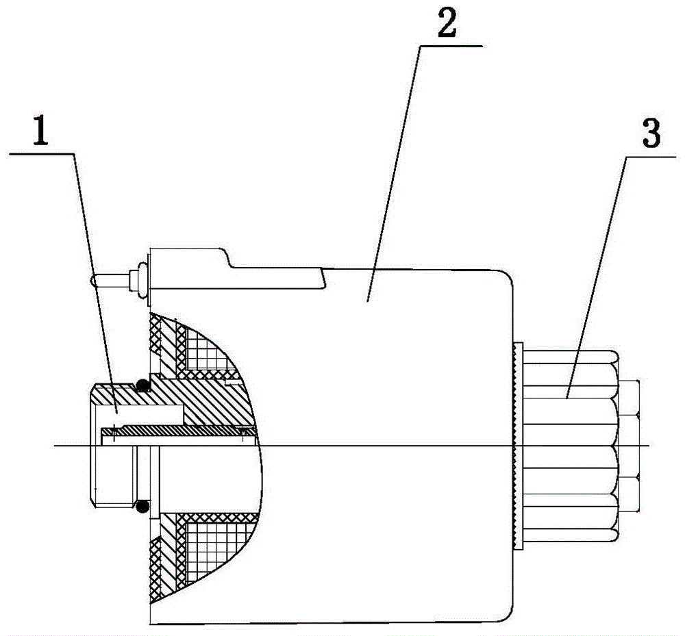
[0022] see Figure 1 to Figure 6 As shown, the solenoid valve electromagnet of the present invention includes a magnetic core tube 1 , a coil 2 and a nut 3 . The magnetic core tube 1 includes an iron core 1.1, a guide sleeve 1.2, an armature 1.3, a push rod 1.4, a manual push rod 1.5 and an end cover 1.6. The guide sleeve 1.2 is connected between the iron core 1.1 and the end cover 1.6, the guide sleeve 1.2 is welded to the iron core 1.1, and the guide sleeve 1.2 and the end cover 1.6 are also welded. The armature 1.3 is slidingly fitted in the inner cavity of the guide sleeve 1.2. The iron core 1.1 is arranged in the axial through hole 1.1.1 communicating with the inner cavity of the guide sleeve 1.2. The push rod 1.4 is arranged in the axial through hole 1.1.1. The manual push rod 1.5 is installed on the end cover 1.6.

[0023] The push ...


PUM


Abstract

The invention discloses an electromagnet for an electromagnetic valve. The electromagnet comprises a magnetic core pipe, a coil and a nut; the magnetic core pipe comprises an iron core, a guide sleeve, an armature, a push rod, a hand-operating push rod and an end cover; the guide sleeve is arranged between the iron core and the end cover; the armature is matched with the inner cavity of the guide sleeve in a sliding manner; the iron core is provided with an axial through hole which is communicated with the inner cavity of the guide sleeve; the push rod is arranged in the axial through hole; the hand-operating push rod is installed on the end cover; the push rod is in a cylindrical shape; the push rod is provided with a first axial oil passage; the outer diameter of two end parts of the push rod is smaller than that of the middle part of the push rod; the side wall of each end part of the push rod is respectively provided with an oil passing hole which is communicated with the first axial oil passage; the armature is provided with a second axial oil passage; the second axial oil passage is communicated with the first axial oil passage; a return spring is arranged between the armature and the end cover. By adopting the electromagnet for the electromagnetic valve, the impact force of the push rod and the armature can be buffered.

Description

technical field [0001] The invention relates to the field of solenoid valves, in particular to an electromagnet for a solenoid valve. Background technique [0002] Solenoid valve is an automatic basic component used to control the direction of fluid, which belongs to actuator. Solenoid valves are usually used in mechanical control and industrial valves to control the direction of the medium so as to control the valve switch. The electromagnet is an important component of the solenoid valve. It acts on the solenoid valve to control the opening and closing of the solenoid valve core. Current electromagnets consist of a core tube, a coil and a nut. The core tube is the core component of the electromagnet. [0003] The magnetic core tube of the electromagnet in the prior art includes an iron core, a guide sleeve, an armature, a push rod, a manual push rod and an end cover. One end of the guide sleeve is connected to one end of the iron core, and the end cover is connected to...

Claims


Application Information

Patent Timeline
Patent Type & Authority Applications(China)
IPC IPC(8): F16K31/06
CPCF16K31/0675
Inventor 刘晓林陈华林陈巍玲
Owner 宁波市鄞州通力液压电器厂
Learn More