A light path system for lighting

An illumination light path and illumination light source technology, applied in the field of microscopes, can solve problems such as unsightly appearance, long illumination light path, difficult installation and debugging, etc. Effect

Active Publication Date: 2016-11-02
MICROFOCUS TECH
View PDF5 Cites 0 Cited by
  • Summary
  • Abstract
  • Description
  • Claims
  • Application Information

AI Technical Summary

Problems solved by technology

[0003] At present, the optical microscope has the following defects: (1) its illumination light path is long, which makes the whole instrument bulky, and the elongated strip shape is neither beautiful nor takes up space; (2) the optical parts on the microscope are fixed in a tube, so that It is very difficult to install and debug; (3) The illumination beam of dark field illumination does not pass through the objective lens, so the contrast of imaging through the objective lens is better, but because the dark field block in the bright field optical path blocks most of the light, and in the long optical path There is a large light loss in the , so the light energy loss is large
In the actual use process, it is found that the required dark field light intensity is about 10 times that of the bright field light intensity, and excessive light intensity will also cause some heat dissipation problems; A light source is required for detection, but the light irradiated by the light source on the object to be detected is not uniform

Method used


Image

  • A light path system for lighting
  • A light path system for lighting
  • A light path system for lighting

Examples


Embodiment Construction

[0041] In order to make the above objects, features and advantages of the present invention more comprehensible, the present invention will be further described in detail below in conjunction with the accompanying drawings and specific embodiments.

[0042]The term "one embodiment" or "embodiment" here refers to that specific features, structures or characteristics related to the embodiment can be included in at least one implementation of the present invention. The appearances of "in one embodiment" in various places in this specification do not necessarily all refer to the same embodiment, nor do they necessarily refer to a separate or selected embodiment that is mutually exclusive of other embodiments. Furthermore, the order of blocks in a method, flowchart, or functional block diagram representing one or more embodiments does not necessarily refer to any particular order nor constitute a limitation on the invention.

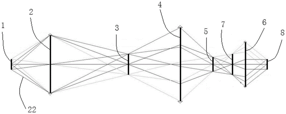
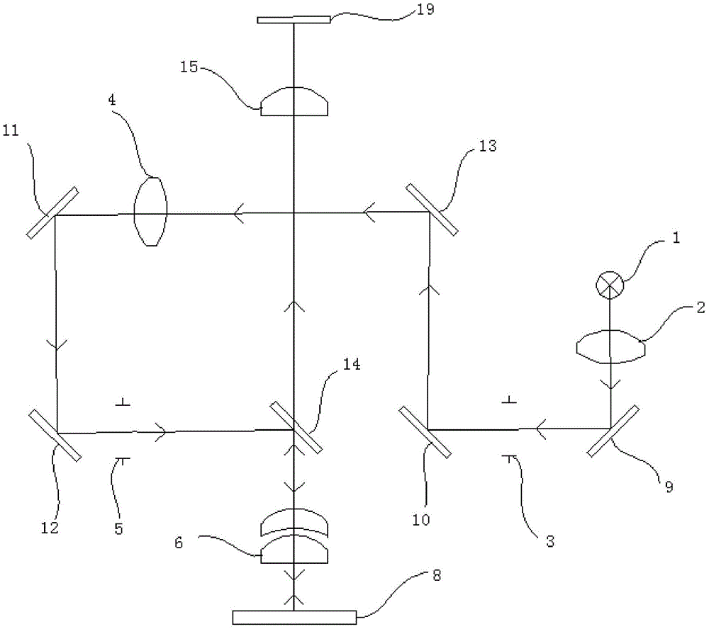
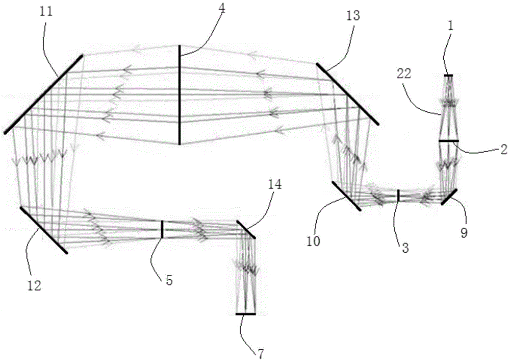
[0043] see figure 1 , which is a schematic diagram of ...


PUM


Abstract

The invention discloses an illumination optical path system. The illumination optical path system comprises a bright field lighting device. The bright field lighting device comprises an illumination light source, a first collecting lens, an aperture diaphragm, a condenser, a view field diaphragm and a first object lens or a first object lens assembly, wherein the aperture diaphragm is disposed between the first collecting lens and the condenser, the view field diaphragm is disposed between the condenser and the first object lens or the first object lens assembly, a light beam generated from the illumination light source, after being collected by the first collecting lens, passes through the aperture diaphragm, the light beam restricted through the aperture diaphragm images the light beam through the condenser and the view field diaphragm on the rear focal plane of the first object lens or the first object lens assembly, and the light beam aggregated to the rear focal plane of the first object lens or the first object lens assembly are emitted in parallel to a detection object through the first object lens or the first object lens assembly so as to form uniform light spots on the detection object. Compared to the prior art, the illumination optical path system has the advantages of short optical path, uniform illumination, high illumination utilization rate and easy installation and debugging.

Description

【Technical field】 [0001] The invention relates to the field of microscopes, in particular to an illumination optical path system. 【Background technique】 [0002] An optical microscope is composed of a stage, an illumination system, an objective lens, an eyepiece, and a focusing mechanism. The focus controller can be used to drive the focus mechanism to make the objective lens move up and down, so that the observed object can be clearly imaged. [0003] At present, the optical microscope has the following defects: (1) its illumination light path is long, which makes the whole instrument bulky, and the elongated strip shape is neither beautiful nor takes up space; (2) the optical parts on the microscope are fixed in a tube, so that It is very difficult to install and debug; (3) The illumination beam of dark field illumination does not pass through the objective lens, so the contrast of imaging through the objective lens is better, but because the dark field block in the brigh...

Claims


Application Information

Patent Timeline
Patent Type & Authority Patents(China)
IPC IPC(8): G02B21/10G02B21/12
CPCG02B21/125
Inventor 何继中
Owner MICROFOCUS TECH
Why Eureka
Try Eureka