

Vehicle lithium ion battery integration module and integration method thereof
A lithium-ion battery, integrated module technology, applied in the direction of batteries, battery pack components, circuits, etc., can solve the problems of increasing the weight of the module, loosening, etc., and achieve the effect of reducing the overall weight and improving reliability.
- Summary
- Abstract
- Description
- Claims
- Application Information
AI Technical Summary
Problems solved by technology
Method used
Image

Examples
Embodiment Construction
[0051] based on the following Figure 2 to Figure 12 , specifically explain the preferred embodiment of the present invention.
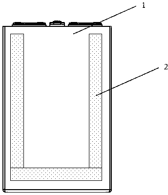
[0052] Such as Figure 11 As shown, the present invention provides a lithium-ion battery integrated module for vehicles, comprising:
[0053] A number of single battery modules, these single battery modules are arranged side by side, and are bonded to each other with structural glue to form an assembled plastic module;
[0054] The single battery module includes:
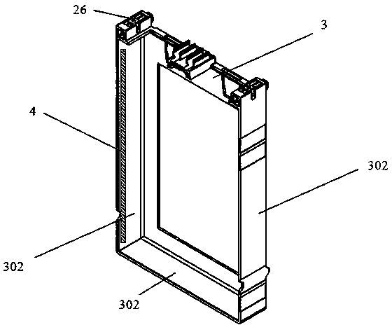
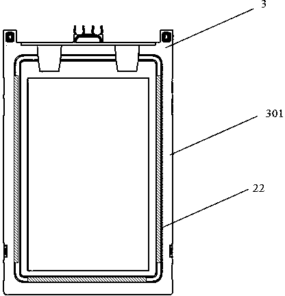
[0055] Thermally conductive frame 3 (made of thermally conductive plastic injection molding, the base material is polyamide PA), such as image 3 with Figure 4 As shown, the heat conduction frame 3 is a frame structure that can accommodate the single battery 1, the heat conduction frame 3 has a hollow bottom plate 301 and a side plate 302 connected to the hollow bottom plate 301, and the inner surface of the side plate 302 is in contact with the side surface of the single battery 1 A...
PUM
| Property | Measurement | Unit |
|---|---|---|
| Thickness | aaaaa | aaaaa |
Abstract
Description
Claims
Application Information